15 years one-stop China custom CNC machining parts factory

Hey there I’m VMT Sam!
With 25 years of CNC machining experience we are committed to helping clients overcome 10000 complex part-processing challenges all to contribute to a better life through intelligent manufacturing. Contact us now
 164 |
Published by VMT at Jan 22 2022
CNC machining is a highly utilized subtractive CNC machining manufacturing technology. Computer numerical control systems offer less manpower requirements and a higher level of automation.
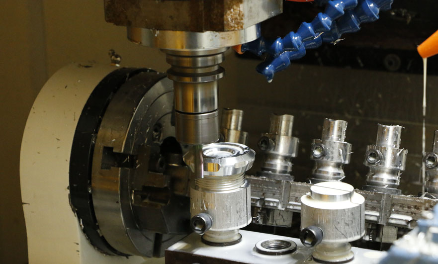
One of the automated manufacturing methods is CNC milling. This is a process in which a rotary tool removes material, making it the opposite of CNC turning.
The CNC milling center not only realizes the automation of cutting, but also realizes the replacement of tools. For example, in the average process of CNC machining from a metal block to a finished product, various tools are used.
To maximize CNC milled part productivity and reliability, mold shops typically machine most CNC milled parts from hardened steel. Historically, hardened steels were rough ground at low feed and low speeds, with large depths of cut and steep slopes.
This CNC milling process is painfully slow and can create deep steps on CNC milled parts, which require multiple semi-finishing and finishing operations. Alternatively, the shop will rough grind a soft block, heat treat it, and bring it back to the mill for a series of semi-finishing and finishing. Another method of machining hardened steel is electrical discharge machining, which is also very time-consuming.
The original error is an error that initially exists in the CNC milling process. The more common ones are geometric error, positioning error, CNC machining error caused by deformation, CNC machining error caused by thermal deformation, and internal stress distribution of CNC milling parts caused by error, etc.
Process System Error
Machine tool geometric errors: Precision CNC machining and milling machines are inseparable from machining accuracy, mainly CNC machining errors, spindle errors, guide rail errors, transmission errors and long-term CNC machining errors.
Tool geometric error: The tool is one of the important part milling machines, and the tool error is an important factor affecting the formation of CNC milling parts to be processed.
Fixture geometric error: Fixture mainly refers to the correct position of CNC parts and tools to be processed. Once the fixture accuracy error occurs, it will affect the accuracy of CNC milling parts.

Positioning error
The datum is not the coincidence error: the error between the position datum and the design datum, if the position and the design datum do not coincide, there will be errors when the adjustment method is used, but there will be no errors in the adjustment process of CNC milling parts.
Trial cut time
Inaccurate CNC manufacturing position: By determining the positioning element, the CNC parts to be processed are in the correct position in the fixture. The positioning error can be the vector sum of the datums, rather than the coincidence and manufacturing position errors.
The horror of transformation
Mechanical CNC Milling Part Stiffness
Compared with machine tools and fixtures, the rigidity of machined CNC parts is lower, and the lack of rigidity caused by deformation during cutting seriously affects the accuracy of CNC milling parts.
Tool stiffness
The stiffness of the outer turning tool is very high on the normal line of the CNC machined surface, and the deformation can be ignored. When the CNC milling part has a small inner hole, the stiffness of the tool bar is poor, which will have a certain impact on the accuracy of the hole.
Stiffness of CNC machined parts
Each mechanical equipment is composed of various CNC milling parts, and the rigidity of the components impacts CNC milling with high precision. The main factors affecting the stiffness of CNC milled parts are the contact deformation of the joint surface, friction effects, low stiffness parts and clearance.
Main declination
The effect of different entering angles on the CNC milling effect is very significant. If a 90° milling cutter is used as a face milling cutter, it is often just because it is easy to use, but its production efficiency or cost efficiency is not as good as that of a 45° milling cutter. CNC milling parts with a 90° milling cutter face instead of a 45° milling cutter reduces productivity by 30%, which in turn directly affects profitability.
Primarily, the entering angle affects the metal removal rate and tool life. Also, as the entering angle decreases, the chip thickness becomes thinner, and as such, there is an opportunity to increase the feed rate to compensate. Now, more and more CNC machining shops use small depth of cut and high feed rate to improve the production efficiency of CNC milled parts, usually using milling cutters with small entering angle (such as 10°), or using milling cutters that can achieve chip thinning Effect of round blade concept. Compared to the 45° face mill, the 10° face mill has an increased feed rate because the chips are thinned to almost one-sixth the size of the 90° face mill. If this strategy results in an insufficient depth of cut, a high feed rate can be used to compensate for the loss of efficiency.
High-feed milling cutters with a 10° entering angle can use very high table feeds due to the thin chips formed. In addition, the high axial cutting force ensures spindle stability and limits vibration, making these CNC milling cutters more suitable for long tool overhangs and/or unstable clamping applications.
For 45° cutters, these are usually the first choice for face milling because they balance radial and axial cutting forces well, and the engagement is very smooth. These milling cutters have low vibration and are suitable for short-chipping materials (such as gray cast iron), which are prone to chipping at the end of the pass because the CNC milling parts are less and less, if the radial force is too large.
Ready To Start Your Next Project?
Get Instant Quote

Request a Free Quote
Send us a message if you have any questions or request a quote. We will get back to you ASAP!