16 years one-stop China custom CNC machining parts factory

Hey there I’m VMT Sam!
With 25 years of CNC machining experience we are committed to helping clients overcome 10000 complex part-processing challenges all to contribute to a better life through intelligent manufacturing. Contact us now
 46 |
Published by VMT at Jul 22 2026 | Reading Time:About 4 minutes
46 |
Published by VMT at Jul 22 2026 | Reading Time:About 4 minutes


When building industrial automation equipments such as aoi inspection stations(automated optical), automated packaging lines or agv warehouse cells, coordinating 300–800 custom machined parts across the whole equipment turns out to be a big roadblock of project rollout. These parts are usually sourced from multiple vendors with inconsistent lead times and disparate QA specifications. One wrong material pick or improperly specified tolerance on a key component or one supplier is unqualified will trigger scrapping during final assembly. This guide breaks down manufacturing risks from the design stage to help you avoid batch defects on the shop floor in advance. A real mass-production case study is attached at the end, illustrating how we resolved flatness out-of-spec scrap issues on sensor mounting brackets through optimized machining processes.
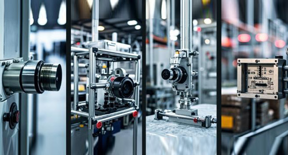
Industrial automation covers a wide spectrum of machinery and automated equipment component manufacturing across diverse sectors:
All these devices share identical core requirements which can meet by CNC machining and its post-treatments : automation equipment parts must maintain precise positioning, transmit motion, route electrical signals, and withstand continuous vibration, washdown and chemical corrosion.
CNC machining for automation equipment leverages 3/4/5-axis milling, turning, EDM and grinding to form solid aluminum bars, plates and billets into finished parts.
Two key distinctions separate CNC machined custom automation components from off-the-shelf standard hardware:
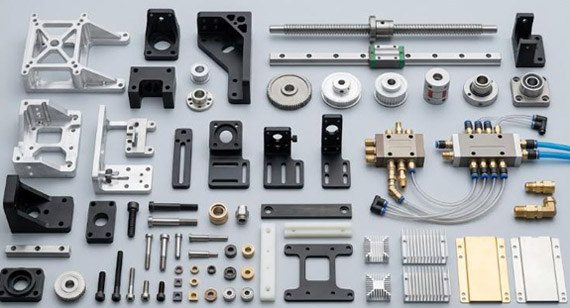
When designing or sourcing parts for a complex automation line, breaking down these parts into functional part categories makes it easier to streamline products and supply management. The table below outlines the seven primary component groups that account for the majority of custom automation equipment parts, complete with material choices and functional tolerance targets:
| Category |
Suggested Materials |
Tolerance Range |
Typical Components |
| Structural Frames & Mounting Brackets | 6061Aluminum, 5052Aluminum, A36 Carbon Steel | ±0.05 mm | Equipment chassis, side protective panels, main mounting baseplates |
| Motion Transmission Components | C360 Brass, 7075Aluminum, 17-4 PH Stainless Steel | ±0.01–0.025 mm | Drive gears, shaft couplings, bearing sleeves, lead nut housings |
| Sensor & Camera Holders | 6061, 7075 Aluminum(Anodized Finish) | Flatness ±0.02 mm | AOI camera plates, photoelectric sensor brackets, encoder bases |
| Pneumatic & Hydraulic Manifolds & Fittings | 303 / 316 Stainless Steel, C360 Brass | ±0.025 mm | Pneumatic valve manifolds, filling nozzles, sealing clamp bars |
| Locating Inserts & Custom Fasteners | 303 Stainless Steel, 17-4 PH Stainless Steel | ±0.025 mm | Anti-loose captive screws, precision alignment pins, threaded inserts |
| Wear-Resistant Guards & Guides | UHMW, Delrin, Hard-Coated Aluminum | ±0.05 mm | Belt guide blocks, tool carriers, metal chip shielding covers |
| Thermal Dissipation & Electrical Shield Parts | 6061 Aluminum, 1100 Aluminum, PEEK | ±0.05 mm | Heat sinks, RF shielding cans, DUT fixture interface plates |
Material choice directly determines machining cycle time, surface finish quality and long-term equipment failure probability. Below are the most widely used industrial materials with their performance:
Modern CNC machining centers can consistently hold tight tolerances within ±0.025 mm, provided the part geometry has no tool access interference and complete datum surfaces are available. You can consider to follow the practical tips: Avoid specifying unnecessarily tight tolerances at the design stage, which saves the production cost a lot; all dimensional limits should align with functional requirements.
Usual Tolerance Values by Functional Feature
| Feature Type |
Tolerance |
Practical Explanation |
| Hole-to-Hole Positionality | ±0.01–0.02 mm | Directly governs overall alignment accuracy of motion frames |
| Mounting Datum Flatness | 0.02–0.05 mm | Core specification for camera and sensor positioning precision |
| Bearing Bore Diameter | ±0.01–0.025 mm | Matches interference press-fit for bearings and bushings |
| General Overall Dimensions | ±0.05 mm | Universal standard for most simple support brackets |
Typical Surface Treatments for Automated Equipment Parts
Baseline QA Protocols that Your Partner Supplier Should Have
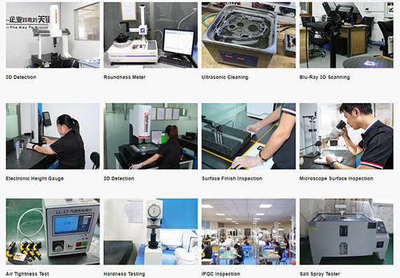
Two popular manufacturing solutions for custom automation equipment parts are compared below. Targeted method selection helps accurately balance lead time and per-unit cost:
| Manufacturing Process |
Lead Time |
Cost Profile |
Optimal Application Scenarios |
| CNC Machining | 2–4 Weeks | Mid per-unit cost, no high NRE fees | Tight tolerance requirements |
| SLS Nylon 3D Printing | 3–7 Days | Higher per-unit cost, no custom tooling fees | Temporary bridge tooling, simple inspection jigs, low-volume complex geometry parts |
| SLA Resin Photopolymer Printing | 2–5 Days | Higher per-unit cost, no custom tooling fees | Visual prototypes |
| DMLS Metal Additive Manufacturing | 1–3 Weeks | Very high per-unit cost, no custom fixtures | Topology-optimized lightweight brackets, metal prototypes pending formal certification |
CNC machining dominates most automation equipment parts, as nearly all machine components require strict dimensional tolerances, material compliance certifications and production volumes ranging from hundreds to thousands of pieces.
Only three scenarios prioritize 3D printing: temporary tooling during CNC program validation, test fixtures requiring frequent design iteration, and prototype parts with intricate internal channels or lattice structures impossible to machine conventionally.
Different industrial automation sectors operate under vastly different environments. Understanding the specific challenges of each sector helps you choose the right materials, tolerances, and surface treatments without over-specifying costs:
Automated Test Equipment (ATE)
Vision Inspection & Optical Equipment
Packaging & Food Processing Automation
Logistics, Palletizing & Warehouse Automation
Specialized Industrial Verticals
Other specialized machinery—including automated agricultural equipment, automated car wash equipment, automated construction equipment, automated electroplating equipment, automated laboratory equipment (automated lab equipment), automated reloading equipment, automated data processing equipment, automated welding equipment, pneumatic automation equipment, and automation equipment for engine-related parts—follow similar design rules:
Customer situation. A mid-sized bakery-automation OEM ran into scrap rates of about 12% on a sensor-mount bracket going into a new dough-handling line. The part was 6061-T6, anodized, with a flatness spec of 0.03 mm on the sensor face.
What the previous supplier missed. The previous vendor machined the part in one operation without a stress-relief pass, then sent it straight for Type II anodize. The coating bath warped the face by 0.04–0.06 mm — outside the 0.03 mm flatness window. The shop also skipped CMM inspection between rough and finish, so the warped baseline propagated into the anodize.
Optimized Machining Process Implemented by VMT
Measurable Improvement Outcomes
Component flatness stabilized within a 0.012–0.018 mm range, fully complying with the 0.03 mm drawing specification. The customer’s incoming QC scrap rate dropped from 12% to 1.2%.
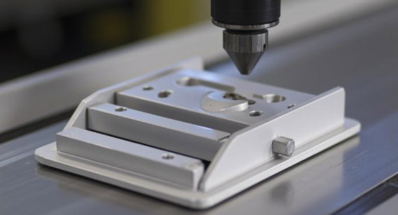
Successfully building complex automation equipment relies on balancing tight dimensional tolerances, selecting function-matched materials, and maintaining strict quality control. By addressing manufacturability risks early in the design stage and working with transparent machining partners who can accommodate rapid iterations without fixture resets, you can avoid batch scrap and keep project rollouts on schedule. Looking for one-stop solution with aluminum, brass, stainless, and engineering-plastic automation equipment parts? For a clean first engagement, send your drawing, target quantities, and a short note on the failure modes the part has to survive (corrosion, fatigue load, FDA contact, and so on). Our engineering team comes back with a manufacturability review within about 2 working days.[2D Drawings (PDF files), 3D Drawings (IGS/STP/STEP files)]
Send your drawings, requirements, and target quantity. VMT will review your project and provide a machining solution and quote.
All information and uploaded files are secure and confidential.
1 Tell us what you need
2 Get solution & quote
3 Approve production
Email: inquiry@vimetal.com.cn
Q1: What standard CNC machined components are used in Automated Test Equipment (ATE)?
ATE fixtures require tight signal routing and zero mechanical play during repeated component probing. Common CNC machined parts include aluminum signal routing plates, non-conductive DUT fixture interface blocks, RF shielding cans, probe alignment blocks, and positioners. They are predominantly machined from 6061-T6 or 5052 aluminum with Type II anodizing, with critical mounting datum flatness held tightly between 0.02 mm and 0.05 mm to prevent pin alignment errors.
Q2: Should packaging equipment frames use aluminum extrusions or steel structural tubing?
Selecting between aluminum and steel depends on mobility requirements and dynamic load conditions. Use 6061/6063 aluminum extrusions if the equipment requires frequent modular reconfigurations or weight reduction for transport, as aluminum is 60–70% lighter than steel. However, choose welded or bolted cold-rolled steel for stationary frames carrying heavy dynamic loads or high-vibration cutting and sealing units, as steel delivers far superior long-term fatigue resistance.
Q3: What materials are standard for warehouse automation and AGV components?
Warehouse AGVs and automated palletizers experience continuous dynamic impacts and high rolling contact friction. Heavy dynamic parts like drive shafts and roller pins use 4140 carbon steel or high-strength 17-4 PH stainless steel. Sensor mounting brackets use lightweight anodized 6061-T6 aluminum, while wear guides, belt tracks, and chip shields default to self-lubricating, impact-resistant engineering plastics like UHMW or Delrin to minimize sliding friction.
Q4: What tolerance range is standard for AOI optical inspection equipment?
Automated vision inspection systems rely on strict optical axis alignment, where even a minor 0.03 mm tilt on a camera plate can distort inspection field-of-view data. Camera mounting surface flatness must hold strictly within 0.02 mm, and critical hole positionality tolerances must hold within ±0.01–0.02 mm.
Q5: Should robotic welding machine parts use CNC machining or 3D printing?
While 3D printing is excellent for temporary bridge tooling and rapid prototypes, functional welding components must be CNC machined. Welding environments subject end-effectors and fixtures to intense thermal radiation, weld spatter, and repeated mechanical cycling. Custom CNC machined parts made from spatter-resistant materials like hard-anodized aluminum, brass, or stainless steel provide the heat dissipation, surface hardness, and clamping rigidity necessary for sustained operations.
Q6: Which surface finishes perform best for optical inspection machinery?
Vision inspection environments require non-reflective surfaces to prevent glare, combined with wear-resistant finishes on moving parts. Matte black Type II anodizing is the standard choice for exterior camera rigs and lighting brackets because it absorbs stray reflections that could trigger vision sensing errors.
The technical information and manufacturing advice shared on the VMT website are for general guidance only. While we strive for accuracy, VMT does not guarantee that the processes, tolerances, or material properties mentioned are applicable to every specific project. Any reliance you place on such information is strictly at your own risk. It is the buyer's responsibility to provide definitive engineering specifications for any production orders. Final specifications and service terms shall be subject to the formal contract or quotation confirmed by both parties.


 +86 15099911516




 Read more