16 years one-stop China custom CNC machining parts factory

Hey there I’m VMT Sam!
With 25 years of CNC machining experience we are committed to helping clients overcome 10000 complex part-processing challenges all to contribute to a better life through intelligent manufacturing. Contact us now
 43 |
Published by VMT at Nov 18 2026 | Reading Time:About 8 minutes


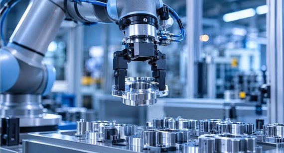
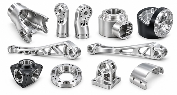
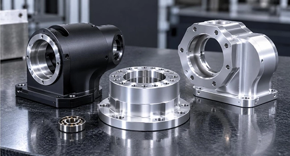
Custom CNC machined robotic end effector components do more than enable robots to perform gripping, handling, and assembly tasks. They also directly affect positioning accuracy, payload capacity, operational stability, and overall efficiency in industrial automation.
This article also presents a case study from our CNC machining factory, where we manufactured a 7075-T6 collaborative robot joint module that achieved a concentricity of 0.008 mm, a housing weight below 180 g, and approximately 40% lower fixture costs.
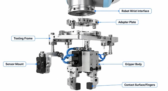
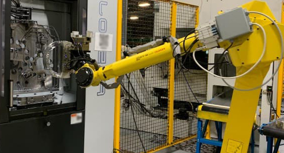
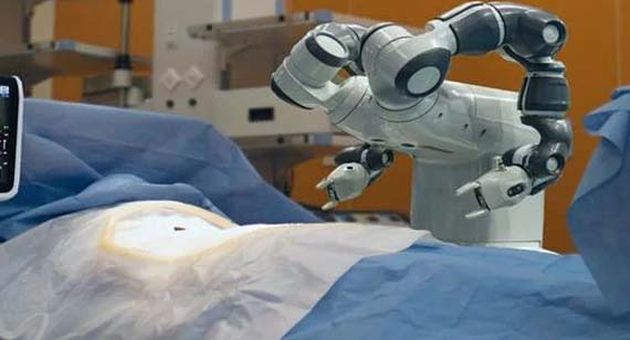
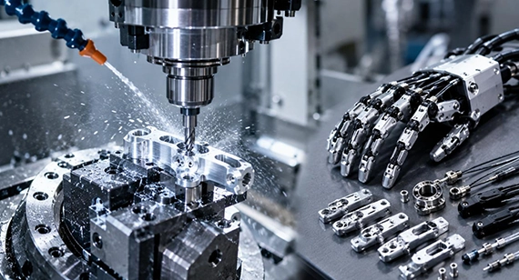
A robotic end effector, also known as end-of-arm tooling (EOAT), is a device mounted on the wrist of a robot. It converts control signals into physical actions to perform specific tasks.
A complete end-of-arm tooling system relies on a precisely assembled mechanical chain, typically consisting of the following components:
These components support a wide range of operations, including gripping, placing, holding, lifting, positioning, assembling, inspection, welding, and grinding.
| Main Task | Corresponding End Effector Components | Common Robot Applications | Key Structural and Machining Requirements |
| Gripping | Gripper Fingers, Gripper Jaws, Gripper Body | Industrial handling robots, collaborative robots | High positioning accuracy, matched gripping profiles, wear resistance |
| Vacuum Picking | Vacuum Manifold, Suction Cup Mounts | Packaging robots, SCARA robots, Delta robots | Air-channel sealing, hole-position accuracy, surface flatness |
| Positioning | Adapter Plates, Tooling Plates, Locating Pins | Assembly robots, collaborative robots | High positional accuracy, flatness, repeatable positioning |
| Handling & Supporting | EOAT Frames, Structural Brackets | Six-axis industrial robots, heavy-payload robots | High structural rigidity, lightweight design, vibration resistance |
| Tool Changing | Tool Changer Interfaces, Locking Components | Multi-process industrial robots, flexible automation systems | Interface fit, reliable locking, repeatable positioning |
| Inspection | Sensor Mounts, Sensor Brackets | Vision inspection robots, collaborative robots | Mounting datum accuracy, structural stability, vibration resistance |
| Welding & Grinding | Tool Holders, Mounting Brackets, Tooling Frames | Welding robots, grinding robots | High rigidity, heat resistance, vibration resistance, mounting accuracy |
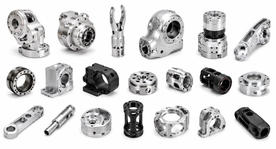
A robotic end effector (EOAT) typically consists of multiple functional components. Different parts handle workpiece gripping, mounting and positioning, pneumatic distribution, and sensor feedback. Depending on the application and payload requirements, their structural designs, machining challenges, and accuracy requirements can vary considerably.
The following are common robotic end effector components and the advantages of CNC machining in their production.
1. Gripper Fingers and Jaws
Gripper fingers and jaws are among the components that come into direct contact with workpieces most frequently. To ensure stable gripping and accurate positioning, their geometry must be designed around the workpiece profile.
2. Robot Gripper Bodies
The gripper body provides the mounting foundation for internal transmission and guiding mechanisms, making structural rigidity particularly important.
3. End-Effector Adapter Plates and Tooling Plates
These components serve as the interface between the robot and its end-of-arm tooling.
4. EOAT Tooling Frames
Tooling frames support multiple end-effector components within a single assembly.
5. Tool Changer Interfaces
Tool changer interfaces allow end-of-arm tools to be switched quickly.
6. Vacuum Manifold Blocks and Suction Cup Mounts
Vacuum manifold blocks distribute airflow throughout the vacuum gripping system.
7. Sensor Mounts and Brackets
Sensor mounts and brackets provide installation points for positioning and inspection sensors.
Material selection for custom CNC machined robotic end effector parts should account for payload, weight, rigidity, wear, corrosion, operating temperature, and machining costs. The following table summarizes commonly used materials and their typical EOAT applications.
| Materials | Key Engineering Advantages | Suitable Robotic End Effector Components |
| 6061-T6 Aluminum | Good machinability, moderate cost, balanced strength-to-weight ratio, good anodizing performance | Gripper bodies, adapter plates, vacuum manifold blocks, sensor brackets |
| 7075-T6 Aluminum | High tensile and yield strength, good fatigue performance, high load-bearing capacity | Heavy-duty supporting frames, high-stress gripping arms, heavy-duty tool holders |
| 304 Stainless Steel | High strength, wear resistance, good impact resistance | Gripper fingertips, wear-resistant guide blocks, heavy-duty locating pins and sleeves |
| 316L Stainless Steel | Excellent corrosion resistance, suitable for acidic, alkaline, and salt-spray environments, suitable for hygienic applications | Medical and sterile pharmaceutical packaging fixtures, structural components for food automation lines |
| POM (Acetal) | Self-lubricating, low friction, good wear resistance, low water absorption, less likely to scratch workpieces | Replaceable contact pads, contoured workpiece supports and locating fixtures, slideway liners |
| PEEK (Engineering Plastic) | Good long-term heat resistance, chemical resistance, low outgassing, excellent electrical insulation | Wafer handling fingers, high-temperature picking fingers, insulating components for specialized environments |
| Grade 5 Titanium (Ti-6Al-4V) | High specific strength, low density, good corrosion resistance and biocompatibility, suitable for high-performance lightweight designs | High-performance robotic gripper fingers, lightweight tool brackets, medical and surgical robotic end-effector components |
| Copper Alloys (Brass / Bronze) | Good electrical and thermal conductivity, with wear and friction-reduction properties in certain grades | Electrical contacts, electrical connection components, specialized sliding bushings |
| Nylon (PA) | Good impact resistance, toughness, and some self-lubricating properties; suitable for lightweight non-load-bearing parts | Gripper contact pads, custom fixtures, cushioning and damping components |
| Carbon Fiber Reinforced Polymer (CFRP) | High specific strength and stiffness, excellent vibration damping, and low thermal expansion depending on fiber layup direction | Lightweight EOAT frames, long-reach tool support structures, high-speed robot wrist components |
| Cast Aluminum Plate (e.g., Mic-6) | Low internal stress and good dimensional stability, suitable for machining large flat structures | Large structural mounting plates, vacuum subassembly base plates, precision tooling plates |
Material selection also needs to reflect how the end effector will operate.
Once the material has been selected, its impact on CNC machining processes and final dimensional stability must also be considered.
For example, aluminum alloys are relatively efficient to machine, but thin-wall structures still require control of cutting heat and clamping deformation. Titanium alloys have low thermal conductivity, so cutting speed, feed rate, and tool wear need to be managed carefully. Engineering plastics are susceptible to temperature and moisture absorption, making post-machining dimensional changes an important consideration.
Large cast aluminum plates such as Mic-6 offer good dimensional stability, but precision mounting holes, threads, and locating interfaces still require secondary CNC machining to achieve the required assembly accuracy. Carbon fiber composites, meanwhile, require suitable cutting tools and machining methods to control delamination and fiber tearing.
The machining quality of custom CNC robotic end effector components depends not only on the dimensional accuracy of individual parts but also on the assembly relationships between multiple components.
| Machining Aspect | Main Components | Key Controls |
| Dimensional Accuracy | Adapter plates, mounting plates | Hole spacing, locating shoulders, locating-pin fits |
| Geometric Tolerances | Grippers, tooling frames | Flatness, parallelism, positional accuracy |
| Surface Quality | Grippers, vacuum manifolds | Surface finish of contact and sealing surfaces |
| Structural Rigidity | Lightweight frames | Thin-wall deformation, bending and torsional resistance |
| Multi-Axis Machining | Contoured grippers, complex manifolds | Multi-face machining, hole-position accuracy, deburring |
Select the Right CNC Machining Process
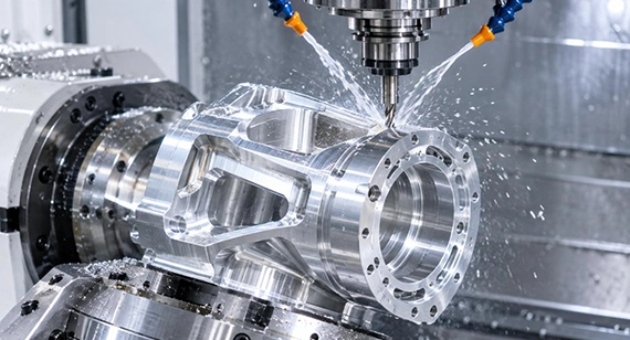
Different end-effector components have different geometries and machining requirements. The appropriate CNC machining process should be selected according to part complexity, the number of machining faces, hole-position relationships, and production volume.
Tip: When most features on robotic end-effector components, such as adapter plates and simple mounting brackets, can be completed using 3-axis machining, there is no need to choose 5-axis machining simply for the sake of using more advanced equipment.
However, for parts with strict positional relationships between holes, multiple angled machining features, or a high risk of errors from repeated setups—such as contoured gripper jaws, robot gripper bodies, and complex EOAT tooling frames—5-axis CNC machining can offer better quality and cost-effectiveness.
Optimize Part Design for Machinability and Rigidity
Robotic end effectors usually need to balance lightweight design with structural rigidity. Excessively reducing wall thickness or adding too many cutouts can lead to machining deformation, insufficient gripping rigidity, and high-frequency vibration during operation.
The following design considerations are worth addressing:
Define Critical Datums and Assembly Tolerances
Robotic end effectors are typically assembled from multiple separately machined components. Meeting the dimensional requirements of each individual part does not necessarily guarantee the accuracy of the complete assembly.
For example, the locating-pin holes between an adapter plate and the robot wrist, the fitting bores between the gripper body and its guiding mechanism, and the mounting datum surfaces between a tooling plate and the end-of-arm tool can all affect final positioning accuracy.
The following points should be addressed during the drawing design stage:
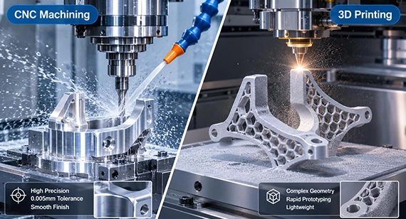
For EOAT components that withstand dynamic loads, require precision assembly of bearings or pins, or need high airtightness, CNC machining is generally the preferred option. For rapid concept validation, complex lightweight structures, or non-critical low-load components, 3D printing offers greater design flexibility and faster production.
In robotic end-effector manufacturing, the two processes each have their own applications.
CNC Machining
Comparison of CNC Machining and 3D Printing
| Comparison Factor | Precision CNC Machining | Industrial 3D Printing |
| Manufacturing Principle | Removes material from metal or plastic stock through cutting | Builds parts layer by layer from powder or filament |
| Tolerances and Fit Accuracy | Precision machining can achieve relatively tight dimensional tolerances (±0.005–0.1 mm), with critical holes and mating surfaces controlled according to drawing requirements | Affected by printing process, material shrinkage, and build orientation (±0.1–0.3 mm); critical holes usually require secondary machining |
| Mechanical Properties | Depend on the material and stock condition; conventional metal stock generally offers good density and stability | Depend on the material, printing process, and interlayer bonding; some processes exhibit anisotropic properties |
| Surface Finish | Finishing operations can achieve good surface quality, making the process suitable for precision mating and sealing surfaces | Layer lines or rough surfaces are common; critical functional surfaces require post-processing |
| Complex Internal Channels | Limited by tool accessibility; complex internal passages may require split-part machining, cross-drilling, or other processes | Can produce complex internal channels and conformal structures, but powder removal, support structures, and cleaning must be considered |
| Lightweight Design | Achieved through milling, thin-wall structures, and reinforcing rib design | Supports topology optimization, lattice structures, and complex lightweight geometries |
| Production Volume | Suitable for repeatable precision parts, small-to-medium batches, and scaled production | Suitable for prototyping, complex low-volume parts, and specialized custom structures |
| Typical Recommended Components | Load-bearing frames, mounting plates, load-bearing grippers, precision vacuum blocks | Rapid interference-check models, low-load pneumatic nozzles, complex conformal suction structures |
For some complex robotic end-effector structures, using CNC machining or 3D printing alone may have limitations.
For example, a complex vacuum gripper may need multiple conformal internal air channels while maintaining high accuracy at its external mounting holes, locating-pin holes, and sealing interfaces.
A hybrid manufacturing process can be considered:
Metal 3D printing is used to produce conformal internal air channels, lightweight structures, and complex external contours.
Mounting datum surfaces, threaded holes, locating-pin holes, and sealing grooves are then finished through secondary CNC machining.
Critical dimensions, interface positions, and surface quality are inspected. Airtightness testing is also performed according to the design requirements.
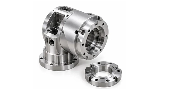
A European collaborative robot manufacturer was developing a new lightweight joint module, and required a one-piece robotic joint housing made from 7075-T6 aluminum alloy. The compact structure needed to integrate a harmonic drive bearing seat, an encoder mounting surface, and a curved internal cable-routing channel.
The concentricity requirement between the harmonic drive bearing seat and the encoder mounting hole was 0.01 mm, while the housing weight had to remain below 180 g. In addition, the internal cable-routing channel needed to be continuous and smooth, with no machining burrs that could damage the cable insulation.
The machining solution therefore needed to address three key challenges: geometric accuracy of the critical bore system, machining quality of the complex internal channel, and dimensional stability of the lightweight thin-wall structure.
Manufacturing Challenges
The main difficulty was maintaining the spatial relationships between multiple critical features.
Our Factory CNC Machining Solution
To address these challenges, our engineering team developed a machining strategy centered on using consistent datums and reducing repeated setups.
Inspection and Project Results
After machining, our team used a coordinate measuring machine (CMM) to verify the geometric accuracy of the critical bores. The internal cable-routing channel was also subject to 100% inspection.
The final inspection results were as follows:
After a validation batch of 200 units, the project secured a follow-on order from the customer covering the next six months. This demonstrated that the machining approach met the customer's needs for transitioning from prototype validation to subsequent batch production.
The final performance of a robotic end effector is not determined by any single component in isolation. It depends on the precision and compatibility of the entire mechanical chain, from the robot wrist interface and main load-bearing frame to the drive body and end-of-arm gripping fingers.
Appropriate material selection, such as aluminum alloy combinations that balance weight and rigidity, controlled geometric tolerances, and carefully machined sealing and contact surfaces are all important to maintaining stable operation after prolonged, high-frequency motion.
Are you dealing with poorly matched custom gripper profiles, angular deviations in adapter plates, minor leaks in vacuum manifold blocks, or end-effector components that add too much weight to the robot payload? Send us your 2D engineering drawings and 3D CAD models to receive a free DFM review and quotation. Our experienced engineers can help optimize part designs for manufacturability, control critical tolerances, and reduce manufacturing costs, helping you build a high-precision, high-rigidity robotic end-of-arm tooling system.[We support 2D Drawings (PDF files), 3D Drawings (IGS/STP/STEP files)].
Send your 2D drawings, 3D CAD models, material requirements, payload targets, robot wrist interface details, locating features, sealing surfaces, gripper or vacuum requirements, surface finishing, prototype quantity and production quantity. VMT will review DFM, process selection, lightweight design, datum strategy, critical tolerances, inspection requirements and quotation details.
All information and uploaded files are secure and confidential.
1 Tell us what you need
2 Get solution & quote
3 Approve production
Email: inquiry@vimetal.com.cn
What Is the Difference Between EOAT and a Robotic Gripper?
EOAT (End-of-Arm Tooling) is a system-level term referring to the complete tooling assembly mounted on a robot's end flange. It can include frames, adapter plates, pneumatic lines, sensors, and actuating mechanisms. A gripper, by contrast, is the specific module that performs mechanical closing and gripping, making it one of the core functional components of a complete EOAT system.
What Are the Main Components of an Industrial Robot?
An industrial robot generally consists of a fixed base, a robotic arm and joints, servo motors and high-rigidity gearboxes, a central controller and teach pendant, and an end-effector system mounted at the wrist to interact directly with workpieces. These components work together to perform programmed movements and operations.
Can CNC Machining Produce Custom Vacuum Manifold Blocks with Complex Internal Air Channels?
Yes. CNC deep-hole drilling can be used to produce intersecting, perpendicular air channels inside aluminum blocks, while threaded plugs seal openings that are not used for airflow. The sealing surfaces can be face-milled to achieve the required finish and flatness. After machining, thorough cleaning and deburring are necessary, followed by pressure-hold testing before shipment to reduce the risk of pneumatic leakage.
How Do You Choose a Reliable EOAT CNC Machining Manufacturer?
Evaluate a manufacturer's engineering and production capabilities across five key areas:
How Do You Prevent Deformation When CNC Machining Thin-Wall EOAT Components?
When machining thin-wall EOAT components, our factory advises customers on appropriate wall thicknesses and reinforcing rib designs. During machining, we use staged cutting, symmetrical material removal, and suitable clamping methods to reduce machining stress. For high-precision components, semi-finishing and finishing operations are also arranged to control deformation after unclamping.
Can Anodizing, or Other Coatings Affect Critical EOAT Fits?
Yes. Some surface treatments create relatively thick coatings, and coating thickness may not be perfectly uniform. For example, with hard anodizing, the 15–25 μm per side allowance is required to help maintain precision mating requirements of ±0.05–0.1 mm for your robotic end-effector components.
But no need to worry about this issue; Our engineering team can recommend suitable surface treatments based on your requirements for appearance, color, texture, corrosion resistance, and wear resistance, and provide masking recommendations and dimensional allowances where necessary.
The technical information and manufacturing advice shared on the machining-custom.com website are for general guidance only. While we strive for accuracy, machining-custom.com does not guarantee that the processes, tolerances, or material properties mentioned are applicable to every specific project. Any reliance you place on such information is strictly at your own risk. It is the buyer's responsibility to provide definitive engineering specifications for any production orders. Final specifications and service terms shall be subject to the formal contract or quotation confirmed by both parties.


 +86 15099911516



 Read more