16 years one-stop China custom CNC machining parts factory

Hey there I’m VMT Sam!
With 25 years of CNC machining experience we are committed to helping clients overcome 10000 complex part-processing challenges all to contribute to a better life through intelligent manufacturing. Contact us now
 57946 |
Published by VMT at Mar 13 2025 | Reading Time:About 5 minutes
57946 |
Published by VMT at Mar 13 2025 | Reading Time:About 5 minutes


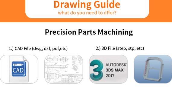
Have you ever looked at an engineering drawing and felt overwhelmed by the symbols and abbreviations? These intricate diagrams contain essential technical details that guide machinists, engineers, and manufacturers in creating precise CNC machined parts. However, understanding them can be challenging, especially for those unfamiliar with standard engineering drawing conventions.
Let’s dive into the fundamentals of engineering drawings, key symbols, and abbreviations, and how they influence CNC machining processes.
An engineering drawing is a technical blueprint used by engineers, machinists, and manufacturers to accurately produce mechanical components. It provides a detailed visual representation of an object, including:
Why are engineering drawings important?
An engineering drawing serves as a universal language between designers and machinists, making it an essential tool in CNC machining and custom part production.

Engineering drawing symbols are standardized notations and graphical representations used in technical drawings to communicate manufacturing specifications, dimensions, tolerances, and surface finishes. These symbols ensure precision and clarity, making them essential in CNC machining, mechanical engineering, and product design.
Why Are Symbols Important?
Each engineering drawing contains a combination of geometry, tolerance, and surface finish symbols to define the exact dimensions, shape, and processing requirements of a component.

Engineering drawings incorporate three main categories of symbols:
Each symbol is critical for ensuring manufacturing accuracy and plays a crucial role in CNC machining and precision part production.
Let’s explore these categories in detail.
1. Geometry Symbols
Geometry symbols are used to define the shape, alignment, and orientation of components in engineering drawings. These include:
These symbols ensure geometric consistency, which is critical in CNC machining and custom part manufacturing.
2. Tolerance Symbols
Tolerance symbols define the allowable variations in dimensions, form, and position. This ensures that CNC machined parts fit together properly without compromising performance.
Accurate tolerancing is crucial in CNC prototype machining to ensure components function correctly and fit seamlessly in assemblies.
3. Surface Finish Symbols
Surface finish symbols define the required texture, roughness, and machining process for a part.
Proper surface finish ensures optimal performance, durability, and appearance in custom CNC machining applications.

Conclusion
Understanding engineering drawing symbols is essential for manufacturers, engineers, and CNC machinists. These symbols provide a universal language for design and production, ensuring that every part is manufactured accurately.
Need high-precision CNC machining services? Contact VMT CNC Machining today!
Engineering drawings use standardized symbols to communicate critical specifications for manufacturing. These symbols define threads, fillets, holes, welding, bends, material types, and machining features such as countersinks and counterbores.
Using these precise notations helps CNC machinists and engineers understand manufacturing requirements at a glance, ensuring accuracy and efficiency in custom CNC machining and CNC prototype machining.
Below are common symbols used in engineering drawings and their meanings.
Thread Symbols
Thread symbols represent screw threads used in fasteners, bolts, nuts, and tapped holes.
Example: M12 × 1.75 – 6H
Proper thread specifications ensure that CNC-machined parts fit correctly in assemblies.
Fillet Radius Symbols
Fillet radius symbols define rounded edges and transitions in engineering drawings.
Fillets improve part durability, while chamfers enhance assembly and handling in CNC machining applications.
Hole Symbols
Hole symbols define drilled, countersunk, counterbored, and tapped holes.
Accurate hole specifications ensure that fasteners fit properly in precision CNC machining parts.
Welding Symbols
Welding symbols specify weld type, size, location, and finish.
Welding symbols help fabricators apply correct joining techniques in metal CNC machining projects.
Bend Radius and Angle Symbols
These symbols indicate how parts should be bent in sheet metal fabrication.
These symbols ensure that bends are accurately formed in sheet metal CNC machining.
Material Symbols
Material symbols indicate what material a part is made from.
Using the correct material symbols prevents misinterpretation in CNC manufacturing.
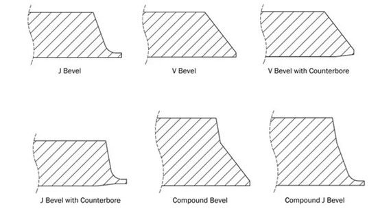
Countersink and Counterbore Symbols
Countersink and counterbore symbols define recessed holes for fastener heads.
These symbols ensure proper seating of fasteners in CNC precision machining.
Conclusion
Mastering engineering drawing symbols is essential for engineers, CNC machinists, and manufacturers. Understanding thread symbols, hole notations, welding signs, bend specifications, and material symbols ensures precision, efficiency, and standardization in CNC machining and custom part manufacturing.
Need high-precision CNC machining services? Contact VMT CNC Machining today!
In engineering and manufacturing, different disciplines use unique sets of symbols to represent components, connections, and specifications. Mechanical engineering drawings use symbols for assemblies, fasteners, and machining instructions, while electrical engineering drawings use symbols to depict circuits, wiring, and electrical components.
Understanding these discipline-specific symbols ensures accuracy in CNC machining, product assembly, and electrical circuit design. Below, we explore mechanical and electrical engineering symbols, their meanings, and applications in CNC machining and manufacturing.
Symbols in Mechanical Engineering
Mechanical engineering drawings contain symbols for parts, fasteners, tolerances, surface finishes, and machining instructions. These symbols are crucial for CNC machining, metal fabrication, and precision manufacturing.
Mechanical Drawing Symbols for Assemblies and Parts
Example:
Proper use of these symbols ensures precision in custom CNC machining.
Common Symbols in Mechanical Drawings
Example:
Mechanical drawing symbols streamline communication in CNC machining and part fabrication.
Symbols in Electrical Engineering
Electrical engineering drawings use symbols to represent circuit components, wiring, and power sources. These symbols ensure accurate electrical system design, troubleshooting, and manufacturing.
Electrical Symbols for Circuits, Wiring, and Components
Power and Voltage Symbols
Resistor and Capacitor Symbols
Switch and Relay Symbols
Wiring and Connection Symbols
Transformer and Inductor Symbols
Diodes and Transistors
Example:
These symbols ensure proper electrical circuit design in electronics manufacturing and CNC machining applications.
Standards for Electrical Engineering Drawings
Electrical drawing symbols follow international standards to ensure compatibility across industries.
By adhering to these standards, manufacturers ensure consistency in CNC machining and electronic manufacturing.
Conclusion
Understanding mechanical and electrical engineering symbols is crucial for accurate CNC machining, electrical design, and manufacturing. These symbols serve as a universal language that eliminates misinterpretation, reduces errors, and ensures efficient production processes.
Need custom CNC machining services with precision manufacturing? Contact VMT CNC Machining today!
Engineering drawing symbols serve as a universal language in manufacturing, CNC machining, and engineering design. They provide essential geometric, dimensional, and machining details, ensuring that engineers, machinists, and manufacturers interpret technical drawings accurately.
Without understanding these symbols, errors in manufacturing, assembly, and quality control can occur. Learning how to read engineering symbols is crucial for precision machining, custom CNC machining, and industrial fabrication.
Step-by-Step Guide to Reading Engineering Drawing Symbols
1. Understand the Title Block
Every technical drawing includes a title block that provides critical details about the component or assembly.
Example:
2. Recognize Geometric Symbols
Geometric symbols define the form, orientation, and location of part features.
Example:
A perpendicularity symbol (⊥) with a 0.05mm tolerance means that the part must not deviate more than 0.05mm from 90°.
3. Interpret Dimensions and Tolerances
Dimensions define sizes, distances, and angles, while tolerances specify acceptable variations.
Example:
Ø25.00 ± 0.02 – A 25mm diameter hole must be between 24.98mm and 25.02mm.
4. Recognize Machining and Surface Finish Symbols
Machining symbols specify how a part should be processed, while surface finish symbols indicate texture and roughness.
Example:
A Ra 3.2 symbol means the surface must have a roughness average of 3.2 micrometers, ensuring smoothness for CNC-machined parts.
5. Identify Welding and Threading Symbols
Example:
M10 × 1.5 – 6H → A metric thread with a 1.5mm pitch and 6H tolerance.
1. Standardized Communication
Engineering drawings use global standards such as ISO, ASME, and ANSI to ensure that manufacturers worldwide interpret designs correctly.
2. Reducing Errors in Manufacturing
Using standardized abbreviations and symbols minimizes misinterpretation, reducing machining errors, assembly defects, and production delays.
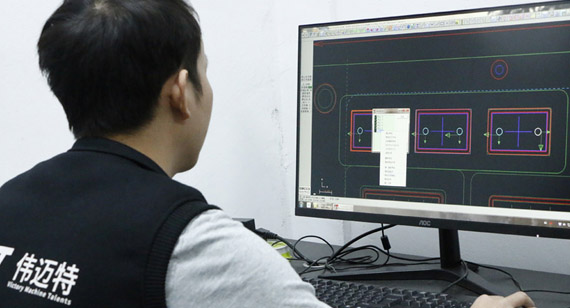
3. Improving CNC Machining Efficiency
CNC machining relies on precise blueprints. Using engineering symbols ensures that machinists follow exact specifications, avoiding rework and scrap material losses.
Conclusion
Reading engineering drawing symbols is an essential skill for engineers, CNC machinists, and manufacturers. These symbols enable standardized, error-free communication, ensuring that parts are precisely machined and assembled.
Need custom CNC machining services with precise engineering drawings? Contact VMT CNC Machining today!
Engineering drawings use standard abbreviations to represent dimensions, tolerances, machining operations, and materials. These abbreviations simplify technical communication and ensure that engineers, machinists, and manufacturers interpret drawings consistently and accurately.
Understanding these abbreviations is essential for CNC machining, custom CNC prototype machining, and precision manufacturing. Below, we provide a detailed guide to the most common abbreviations used in engineering drawings.
Common Abbreviations in Engineering Drawings
DIM (Dimension)
Why It’s Important:
Ensures that all features are machined to the correct size in CNC machining services.
TOL (Tolerance)
Why It’s Important:
Ensures tight control over CNC machining accuracy, reducing manufacturing errors.
ISO (International Organization for Standardization)
Why It’s Important:
Ensures consistency in CNC machining parts manufacturing across different industries worldwide.
Radius ‘R’
Why It’s Important:
Improves part durability by reducing stress concentration in machined components.

Spherical Radius ‘SR’
Why It’s Important:
Essential for machining curved surfaces in aerospace and medical applications.

Diameter ‘Ø’
Why It’s Important:
Crucial for CNC turning and drilling operations, ensuring accurate hole placement and fit.

Spherical Diameter ‘SØ’
Why It’s Important:
Used in ball joints, bearings, and aerospace components where curved precision is required.
Square ‘□’
Why It’s Important:
Used for precision-cut parts in CNC milling and sheet metal fabrication.

Thickness ‘t’
Why It’s Important:
Essential for sheet metal CNC machining and laser cutting operations.

45 Degree Chamfer ‘C’
Why It’s Important:
Ensures smooth transitions between surfaces, improving part assembly and handling.
BOM (Bill of Materials)
Why It’s Important:
Critical for supply chain management and CNC machining production planning.
CSK (Countersink)
Why It’s Important:
Ensures flush screw fitting in CNC-machined parts.
C.Bore (Counterbore)
Why It’s Important:
Provides a clean, flush fit for bolt heads in CNC machining.
TBD (To Be Determined)
Why It’s Important:
Used in prototype machining and product development when certain parameters are pending final design approval.
LD (Length Dimension)
Why It’s Important:
Ensures that CNC-machined parts match assembly requirements.
Conclusion
Engineering drawing abbreviations are essential for accurate CNC machining, fabrication, and quality control. Understanding these abbreviations ensures precise manufacturing, cost efficiency, and reduced errors in custom CNC machining services.
Looking for high-quality CNC machining parts? Contact VMT CNC Machining for precision manufacturing solutions!
Why VMT is the Right Choice for CNC Machining?
When it comes to precision CNC machining, choosing the right CNC machining service provider is crucial. VMT CNC Machining stands out as a leading manufacturer specializing in custom CNC machining, CNC prototype machining, and high-precision CNC machining services. Our state-of-the-art CNC machining factory is equipped with advanced machinery and skilled professionals to ensure that your projects meet the highest industry standards.
Whether you need custom aluminum CNC machining parts, brass CNC machining parts, titanium components, or plastic prototypes, VMT provides high-quality, cost-effective solutions to fit your engineering and manufacturing needs.
What Makes VMT CNC Machining Stand Out?
1. Advanced CNC Machining Technology
At VMT CNC Machining, we utilize the latest CNC milling, CNC turning, laser cutting, and precision machining technologies. Our machines support multi-axis machining, ensuring high precision and complex geometries in every project.
Result: Faster production times, improved accuracy, and reduced material waste.
2. High-Quality CNC Machined Parts with Tight Tolerances
VMT ensures that all CNC machined parts meet the strictest quality standards, with tolerances as tight as ±0.005mm.
Result: Your parts will be defect-free, durable, and ready for immediate use.
3. Wide Range of Materials for CNC Machining
VMT specializes in machining various metals and plastics, ensuring the right material selection for your application.
Result: The best material selection for strength, weight, corrosion resistance, and cost efficiency.
4. Competitive CNC Machining Prices
VMT offers cost-effective solutions without compromising quality.
Result: High-quality CNC machining at affordable rates.
5. Fast Lead Times & On-Time Delivery
We understand the importance of fast turnaround times in manufacturing. VMT CNC Machining ensures that your parts are delivered on schedule.
Result: Your CNC machined parts are ready when you need them.
6. One-Stop CNC Machining Services
From prototyping to full-scale production, VMT provides a comprehensive range of CNC machining services.
Result: A complete manufacturing solution under one roof.
7. Strict Quality Control & Inspection
VMT follows a rigorous quality control process, ensuring that each part meets industry standards.
Result: Zero-defect CNC machined parts with guaranteed performance.
Get Your CNC Machined Parts from VMT Today!
If you're looking for high-quality CNC machining services, VMT is your trusted partner. We specialize in:
Why Choose VMT?
Request a Quote Today!
Contact VMT CNC Machining and get an instant quote for your CNC machining project!

Engineering drawing symbols and abbreviations play a crucial role in manufacturing, design, and CNC machining. Understanding these symbols ensures efficient communication, precise machining, and accurate fabrication. Below are answers to the most frequently asked questions about engineering drawing symbols.
1. What is the ISO standard for CAD drawings?
The ISO 128 standard governs technical drawings, including CAD drawings. This international standard defines line thickness, dimensioning rules, and graphical representation for engineering designs.
Other relevant ISO standards for CAD drawings include:
Why It’s Important: Ensures global consistency in technical drawings for CNC machining, custom machining, and industrial manufacturing.
2. What are the 7 types of lines in technical drawings?
Technical drawings use different line types to represent features such as edges, dimensions, and hidden parts.
Why It’s Important: Correctly interpreting lines prevents machining errors and ensures accurate part production.
3. What are the common symbols for drawing ER diagrams?
Entity-Relationship (ER) diagrams are used in database and system design.
Why It’s Important: Helps engineers and developers visualize data structures for software and product design integration.
4. What is the symbol for thickness?
The standard symbol for thickness in engineering drawings is ‘t’.
Why It’s Important: Used in sheet metal CNC machining, casting, and laser cutting.
5. What is a drawing symbol?
A drawing symbol is a graphical representation used to communicate features, dimensions, tolerances, surface finishes, and welding details in technical drawings.
Why It’s Important: Helps machinists interpret technical drawings quickly and accurately.
6. What are the symbols in sketches?
Sketches use standard symbols to represent dimensions, surfaces, and geometric relationships.
Why It’s Important: Guides machinists and engineers in CNC prototype machining and fabrication.
7. What does OD mean in drawings?
Why It’s Important: Essential for CNC turning and lathe operations.
8. What is SR in engineering drawings?
Why It’s Important: Used in ball joints, bearings, and aerospace components.
9. What does F stand for in engineering?
Why It’s Important: Used in structural calculations and CNC surface finishing.
10. What does RF mean in engineering drawings?
Why It’s Important: Helps engineers understand approximate sizes without strict tolerances.
11. What is AC in drawing?
Why It’s Important: Used in fasteners, hex bolts, and CNC machining of prismatic parts.
12. What are the three main types of technical drawings?
Why It’s Important: Helps CNC machinists and fabricators interpret part geometry accurately.
13. What are hidden lines on engineering drawings?
Why It’s Important: Prevents assembly errors in CNC machining and fabrication.
Conclusion
Understanding engineering drawing symbols and abbreviations is essential for manufacturing, CNC machining, and mechanical design. These symbols standardize communication, reduce errors, and improve production efficiency.
Looking for high-quality CNC machining services with precise engineering drawings? Contact VMT CNC Machining today for expert solutions!

 +86 15099911516


 Read more