16 years one-stop China custom CNC machining parts factory

Hey there I’m VMT Sam!
With 25 years of CNC machining experience we are committed to helping clients overcome 10000 complex part-processing challenges all to contribute to a better life through intelligent manufacturing. Contact us now
 3418 |
Published by VMT at Mar 14 2025 | Reading Time:About 4 minutes
3418 |
Published by VMT at Mar 14 2025 | Reading Time:About 4 minutes


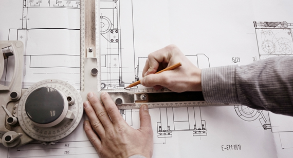
Engineering drawings are the backbone of manufacturing and CNC machining, serving as the universal language between designers, engineers, and machinists. However, poorly executed drawings can lead to miscommunication, machining errors, and increased production costs.
Many engineers and designers struggle with creating clear, precise, and functional engineering drawings. The challenges often stem from over-dimensioning, lack of standardization, unclear tolerances, and missing annotations. Without proper technical drawing skills, projects can experience delays, rework, and financial losses.
The solution? Mastering engineering drawing principles by understanding symbols, line types, tolerances, and dimensional standards. This guide will help you refine your drawing techniques and ensure your designs meet industry and CNC machining standards.
Engineering drawing is a technical representation of an object or system, using lines, symbols, dimensions, and annotations to convey manufacturing and assembly instructions. It is a crucial aspect of CNC machining, mechanical design, and custom manufacturing.
An effective engineering drawing must be:

Engineering drawings serve multiple purposes in manufacturing, CNC machining, and mechanical design:
Why Are Engineering Drawings Essential?
Engineering drawings are the foundation of manufacturing, CNC machining, and product design. Without a clear and precise technical drawing, machinists and fabricators may misinterpret dimensions, tolerances, or material requirements, leading to errors, costly rework, and production delays.
Many engineers and designers struggle with creating accurate, standardized, and readable engineering drawings. Issues such as incorrect line usage, missing dimensions, improper tolerancing, and unclear annotations can lead to severe manufacturing defects.
The solution? Mastering the fundamentals of engineering drawing through proper line types, views, dimensions, tolerances, and symbols. This guide will walk you through the step-by-step process of drawing engineering drawings that meet industry standards.
Step 1: Understand the Purpose of the Engineering Drawing
Before you start sketching, determine the goal of the drawing:
Tip: Always ensure the drawing conveys all necessary information clearly, avoiding unnecessary details that clutter the layout.
Step 2: Select the Appropriate Drawing Views
Engineering drawings require multiple views to describe an object completely. The most common types include:
Isometric View – A 3D representation of the part, showing three sides at once.
Orthographic View – The standard projection method, including:
Sectional View – A cutaway view to show internal details.
Detailed View – Enlarged view of small or complex features.
Auxiliary View – Used to show angled surfaces that are not clear in standard views.
Tip: For CNC machining parts, orthographic views with sectional details are preferred for accuracy.
Step 3: Use the Correct Line Types
Lines in engineering drawings convey different meanings:
Tip: Consistent line usage ensures readability and prevents misinterpretation.
Step 4: Add Dimensions and Tolerances
Proper dimensioning is critical for accurate machining and manufacturing.
Tip: For precision CNC machining, apply realistic tolerances based on ISO 2768 or ASME Y14.5 GD&T standards.
Step 5: Include Material Specifications and Surface Finish
Every engineering drawing should include material details to guide machinists and suppliers:
Tip: CNC machining factories require clear material and finish details to optimize processing steps.
Step 6: Create a Title Block for Documentation
A title block provides important reference information about the drawing:
Tip: A well-structured title block improves traceability in CNC prototype machining and manufacturing documentation.
Step 7: Standardize Your Drawing Format
To ensure consistency across all engineering drawings, follow international drawing standards:
Tip: Standardization ensures CNC machining services can interpret and manufacture parts correctly.
Conclusion: Master Engineering Drawing for CNC Machining
Engineering drawings are the blueprints of manufacturing—they must be precise, readable, and standardized. By mastering technical drawing principles, engineers and designers can improve machining accuracy, reduce errors, and optimize production efficiency.
At VMT CNC Machining, we specialize in high-precision custom CNC machining services, ensuring your engineering drawings are flawlessly executed into high-quality parts.
Need expert CNC machining services? Contact us for a quote today!
Engineering drawings are the universal language of manufacturing, providing precise instructions for CNC machining, fabrication, and assembly. These drawings must be clear, accurate, and standardized to avoid manufacturing errors, misinterpretation, and costly rework.
The basic components of engineering drawings—including lines, views, dimensions, and annotations—form the foundation of technical design and CNC machining processes. Understanding these elements ensures better communication between engineers, designers, and machinists.
Types of Lines in Engineering Drawings
Lines are the building blocks of engineering drawings, each serving a specific function. Proper line usage ensures clarity and prevents errors in interpretation.

1. Visible Lines (Object Lines)
2. Hidden Lines
3. Center Lines
4. Dimension Lines
5. Cutting Plane Lines
Tip: Consistent and correct line usage improves drawing readability and prevents machining errors.
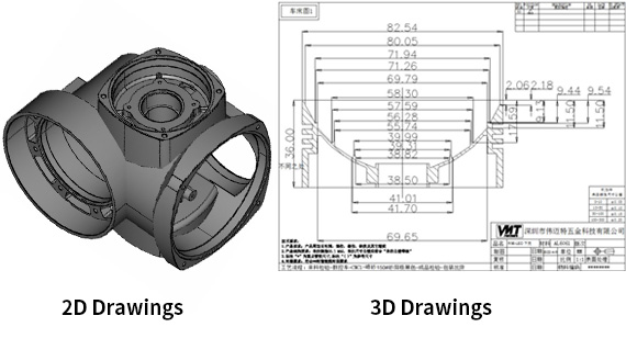
Different Types of Drawing Views
Engineering drawings use various views to represent complex parts in a standardized manner. These views help machinists and engineers visualize and interpret the component effectively.
1. Isometric Views

2. Orthographic Views (Multi-View Projection)

3. Cutout View

4. Detailed Views

5. Auxiliary Views
Tip: Orthographic and section views are most commonly used in CNC machining drawings.

Aspects of Engineering Drawings
1. Dimensioning and Tolerances
2. Surface Finish Specifications
3. Material Specifications
Information Blocks in Engineering Drawings
Title blocks provide essential reference information about the drawing and part specifications.
1. Title Block
Located in the lower right corner of the drawing sheet.
Includes:
2. Revision Block
3. Notes and Callouts
Tip: A well-organized title block improves documentation and traceability in CNC machining projects.
Conclusion: Mastering Engineering Drawing Components
A strong understanding of engineering drawing basics—including line types, views, dimensions, tolerances, and title blocks—is crucial for effective communication in manufacturing and CNC machining services.
At VMT CNC Machining, we specialize in custom CNC machining services and precision part manufacturing based on detailed engineering drawings.
Need expert CNC machining for your project? Contact us today for a quote!
Why Are Well-Defined Engineering Drawings Essential?
Engineering drawings serve as the blueprint for CNC machining, fabrication, and assembly. However, poorly defined drawings can lead to manufacturing errors, delays, and increased costs.
Many designers struggle with over-dimensioning, missing callouts, unclear tolerances, and unnecessary annotations—issues that confuse machinists and increase production risks.
The solution? Optimizing your engineering drawings by applying best practices for dimensions, callouts, and tolerances. This guide highlights key tips for improving clarity, precision, and manufacturability.
Tip 1: Include Dimensions Only for Critical, Measurable Features
Overloading a drawing with unnecessary dimensions leads to clutter, confusion, and increased chances of misinterpretation.
Example: Instead of dimensioning every minor radius and edge, focus on hole locations, overall part size, and key functional features.

Tip 2: Add Tap Requirements to Drawings
Threaded holes are common in CNC machining, but failure to define tapping details leads to assembly failures.
Example: Instead of just writing M10, use "M10 × 1.5, depth 20 mm, blind hole" for clarity.

Tip 3: Incorporate Callouts for Machining Instructions
Callouts provide critical instructions that help machinists understand special machining, surface finishes, or coatings.
Example: Instead of vague notes like "smooth finish", use "Ra 0.8 µm on sealing surfaces".
Tip 4: Communicate Assembly Intent for Critical Features
When a part is part of an assembly, its function and fitment must be clear to avoid compatibility issues.
Example: Instead of assuming a machinist knows which surfaces require precision, use datum references and GD&T to define exact positioning.
Tip 5: Part Numbers Are Important
Every drawing should clearly define part numbers to ensure traceability and prevent assembly confusion.
Example: Instead of using generic labels, use "Part No: VMT-12345, Rev B" for easy identification.
Tip 6: Don’t Include Optional Secondary Operation Callouts
Avoid unnecessary callouts for optional operations, as they create ambiguity and confusion.
Example: Instead of writing "Tapping available upon request", create a separate revision for tapped and untapped versions.
Tip 7: Avoid Over-Dimensioning or Over-Tolerancing Designs
Excessive dimensions or tight tolerances lead to higher machining costs and increased rejection rates.
Example: Instead of "All dimensions ±0.01 mm", use "Only shaft diameter Ø25 ±0.01 mm, all others ISO 2768-mK".
Tip 8: Ensure Tolerances Are Within Standard Accuracy Levels
Unrealistic tolerances increase production costs and may be impossible to achieve with standard machining.
Example: Instead of specifying ±0.005 mm tolerances everywhere, apply GD&T to control only critical features.
Conclusion: Engineering Drawings for CNC Machining Success
Engineering drawings must be precise, readable, and optimized for manufacturing efficiency. By following these best practices, engineers can reduce errors, improve communication with machinists, and streamline CNC machining operations.
At VMT CNC Machining, we specialize in high-precision CNC machining services using accurate engineering drawings.
Need CNC machining services for your custom parts? Contact us today for a quote!
Why Optimize Your Engineering Drawings?
Engineering drawings are the foundation of CNC machining, manufacturing, and fabrication processes. However, poorly optimized drawings can lead to production delays, higher machining costs, and unnecessary rework.
Many engineers and designers struggle with over-complicated dimensioning, unclear annotations, and excessive tolerancing, which often result in increased machining costs and wasted materials.
The solution? By applying these 10 essential tips, you can streamline your engineering drawings, reduce production costs, and improve communication with manufacturers.
#1: Rules for Drawing Lines
Lines are the backbone of engineering drawings. Each type of line serves a distinct function, and using the correct line types ensures clarity and prevents machining errors.
Continuous Lines
Hidden Lines
Center Lines
Broken Lines
Cutting Plane Lines
Tip: Using the correct line type in your CAD drawings helps machinists interpret parts accurately and avoid manufacturing mistakes.
#2: Consider Key Dimensional Features
Precise and well-organized dimensions ensure efficient and accurate machining. Over-dimensioning or missing critical dimensions leads to manufacturing errors and increased production costs.
Datum References
Dimensioning
Tolerances
Thread Information
Tip: Use standard tolerances wherever possible to minimize CNC machining costs and lead times.
#3: Assembly Design Considerations
Tip: Communicating assembly intent reduces the risk of misalignment and part rejection.
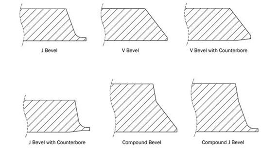
#4: Clearly Define Tap and Threaded Hole Details
Tip: Always mention countersink (CSK) or counterbore (C.Bore) details if required.
#5: Avoid Redundant Dimensioning
What is Redundancy?
Avoid Common Redundancies
Tip: A clear and simplified drawing speeds up CNC programming and machining.
#6: Provide Realistic Tolerances
Tip: If standard tolerances work, don’t overcomplicate the design with unnecessary tight constraints.
#7: Coordinate with Your CNC Machining Service Provider
Machinists and manufacturers often have input on design improvements that can reduce costs and improve manufacturability.
Discuss key factors with your supplier:
Tip: Early collaboration with manufacturers prevents design revisions and unexpected costs.
#8: Use Multiple Drawings for Complex Parts
Tip: Breaking complex designs into multiple sheets improves communication with machinists.
#9: Add Self-Explanatory Notes and Title Blocks
Every drawing should have a well-organized title block with:
Tip: A properly structured title block improves traceability and ensures clarity.
#10: Standardize Your Drawings
A consistent format and layout ensures efficient processing and understanding of engineering drawings.
Follow the T-B-C-C method for optimized drawings:
Tip: Adopting a standardized drawing format improves efficiency across design and manufacturing teams.
Conclusion: Engineering Drawing Optimization for CNC Machining
By applying these 10 engineering drawing best practices, you can streamline design, reduce machining costs, and improve part accuracy.
At VMT CNC Machining, we specialize in custom CNC machining services using precise and optimized engineering drawings.
Need CNC machining for your project? Contact us today for expert consultation and rapid production!
Engineering drawings are the universal language of manufacturing, serving as the blueprint for CNC machining, fabrication, and assembly. A clear, concise, and well-structured drawing reduces errors, ensures accurate production, and ultimately saves time and cost.
By applying the 10 best practices outlined in this guide, engineers and designers can eliminate common mistakes, improve manufacturability, and streamline communication with manufacturers.
Key Takeaways
Engineering drawings are not just technical documents—they are the foundation of precision manufacturing. Whether designing simple components or complex assemblies, following these principles enhances efficiency, reduces production costs, and ensures high-quality final products.
At VMT CNC Machining, we specialize in CNC machining services that rely on accurate and optimized engineering drawings. Our team is dedicated to helping engineers and manufacturers transform designs into high-precision machined parts.
Looking for expert CNC machining services? Contact us today for a professional consultation and fast, high-precision production!

How to learn engineering drawing well?
To learn engineering drawing effectively, start by understanding basic drawing principles, line types, geometric symbols, and dimensioning techniques. Practice by creating simple sketches and progress to complex technical drawings using CAD software. Referring to standards like ISO 128 and ASME Y14.5 helps in understanding best practices.
How to learn engineering drawing easily?
Engineering drawing can be learned more easily by breaking it into smaller concepts. Focus on basic geometric shapes, projections, and dimensioning techniques before moving to tolerancing and GD&T (Geometric Dimensioning and Tolerancing). Using visual learning resources like CAD tutorials, engineering textbooks, and hands-on practice helps reinforce concepts.
How to learn engineering drawing quickly?
To speed up the learning process, use online courses, CAD software tutorials, and real-world case studies. Start with manual sketching to understand fundamentals, then move to digital CAD software like AutoCAD, SolidWorks, or Fusion 360. Practicing daily and working on real projects will accelerate your learning.
What does Ø mean in engineering?
The symbol Ø represents diameter in engineering drawings. It indicates the size of circular features such as holes, cylinders, and rods. Example: Ø10 mm means a hole or cylinder with a 10 mm diameter.
What is Φ in drawing?
The symbol Φ (Phi) is sometimes used interchangeably with Ø to indicate diameter in certain drawing conventions. However, Ø is the preferred symbol for diameter in most engineering standards.
Is Ø the same as Ø?
Yes, Ø is always used to represent the diameter of a feature in engineering drawings, regardless of its context.
How do I pronounce Ø?
In engineering and technical terms, Ø is pronounced as “diameter”. Example: Ø20 mm would be spoken as “diameter 20 millimeters”.
Does Ø mean diameter or radius?
Ø specifically refers to the diameter of a circle or cylindrical object. If a radius is needed, the symbol “R” (e.g., R10 mm) is used instead.
What is Ø used for?
Ø is used in technical drawings to specify the diameter of holes, shafts, and other cylindrical features.
What does Ø symbolize?
It symbolizes circular dimensions in engineering drawings and is commonly used for specifying hole sizes, shaft diameters, and round features.
What does Ø mean in physics?
In physics, Ø is sometimes used to denote angular displacement, null set (in mathematics), or diameter in technical contexts. However, its primary meaning in engineering remains “diameter.”
What are the typical features in engineering drawings?
Common features in engineering drawings include:
Do all drawings need datums?
Not all drawings require datums, but for precision CNC machining and GD&T applications, datums are essential for defining reference points, ensuring part consistency, and aligning features correctly.
What are CAD drawings called?
CAD (Computer-Aided Design) drawings are often referred to as:
Need precise CNC machining based on engineering drawings? Contact VMT CNC Machining for expert consultation and fast production!

 +86 15099911516


 Read more