16 years one-stop China custom CNC machining parts factory

Hey there I’m VMT Sam!
With 25 years of CNC machining experience we are committed to helping clients overcome 10000 complex part-processing challenges all to contribute to a better life through intelligent manufacturing. Contact us now
 1735 |
Published by VMT at Mar 17 2025
1735 |
Published by VMT at Mar 17 2025


In the world of precision engineering and CNC machining, achieving accurate part dimensions is essential. Geometric Dimensioning and Tolerancing (GD&T) is a universal engineering language that ensures parts are manufactured correctly and fit together seamlessly. Without a standardized way to define tolerances, inconsistencies can lead to assembly issues, quality control problems, and increased production costs.
If you’ve ever struggled with unclear tolerances, GD&T is the solution. It helps engineers and manufacturers communicate precise design intent, ensuring parts function as intended. By understanding GD&T symbols and their applications, you can improve design efficiency, reduce errors, and optimize production.
GD&T (Geometric Dimensioning and Tolerancing) is a symbolic system used in engineering drawings to define part geometry, tolerances, and functional relationships between features. Unlike traditional dimensioning methods, which rely solely on linear and angular tolerances, GD&T offers a more precise way to control shape, orientation, and location.
GD&T is governed by ASME Y14.5 and ISO 1101 standards, which ensure uniformity across industries. It allows manufacturers to define the allowable variation in form and position, ensuring components assemble correctly and perform as expected.
In modern engineering, CNC machining, and precision manufacturing, accuracy and consistency are critical. Geometric Dimensioning and Tolerancing (GD&T) provides a standardized method for defining tolerances, ensuring seamless assembly, efficient manufacturing, and reduced production costs.
Without GD&T, misinterpretations of design intent can lead to assembly failures, part misalignment, and unnecessary rework, increasing waste and operational expenses. Implementing GD&T improves product quality, reduces inspection times, and enhances communication across design and manufacturing teams.
1. Excellent Assembly

One of the primary benefits of GD&T is ensuring parts fit together correctly in an assembly. Unlike traditional dimensioning, which only controls size and location, GD&T considers form, orientation, and positional accuracy, preventing misalignment and improving functional fit.
By minimizing tolerance conflicts, GD&T allows manufacturers to maintain high accuracy without increasing production complexity, making it ideal for automotive, aerospace, medical, and industrial applications.
2. Universally Understandable
GD&T is a standardized system used globally in manufacturing industries, governed by:
Using GD&T eliminates misinterpretations caused by different manufacturing practices and ensures clear communication between designers, machinists, and quality inspectors.
When design specifications are clear and universally understood, production efficiency improves, leading to faster project completion and reduced lead times.
3. Saves Time and Money
By reducing unnecessary precision requirements, GD&T allows for looser tolerances where possible, minimizing manufacturing complexity and cost.
For example, using true position tolerance instead of linear dimensioning can significantly improve machining flexibility while maintaining functional accuracy. This leads to:
Conclusion
GD&T is an essential tool for precision manufacturing, ensuring accurate assembly, universal communication, and cost-effective production. By implementing GD&T in CNC machining and engineering design, manufacturers can improve product reliability, reduce errors, and streamline the entire manufacturing process.
At VMT CNC Machining, we apply GD&T-compliant techniques to deliver high-quality, precision CNC machined parts, ensuring that every component meets exact specifications.
Need precision CNC parts with GD&T-defined tolerances? Contact us today for expert consultation and high-performance manufacturing solutions!
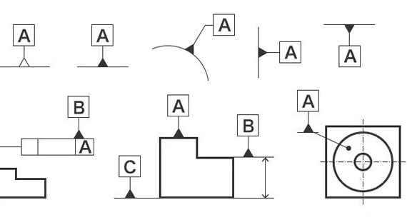
Geometric Dimensioning and Tolerancing (GD&T) is a symbolic language used in engineering and CNC machining to define part features, tolerances, and functional requirements precisely. Unlike traditional dimensioning, which only defines size and basic location, GD&T accounts for form, orientation, and positional relationships to ensure proper function and fit during manufacturing and assembly.
By using GD&T symbols, datums, and tolerance zones, engineers can communicate clear, consistent, and universally accepted design specifications, reducing errors, misinterpretations, and costly rework in the manufacturing process.

1. Establishing a Datum System
A datum is a theoretical reference point, axis, or plane from which all dimensions and tolerances are measured. Datums serve as the foundation for ensuring accurate part alignment and assembly fit.
Example: In a CNC machined housing, the base surface (Primary Datum) ensures stability, the side walls (Secondary Datum) ensure alignment, and the top face (Tertiary Datum) ensures correct height positioning.
Why is this important?
2. Applying GD&T Symbols to Define Tolerances
GD&T uses a set of symbols and feature control frames to define allowable variations in form, orientation, location, and profile.
Example: A hole in a part must be positioned precisely within a ±0.1 mm tolerance to ensure correct alignment during assembly. Instead of defining X and Y linear tolerances separately, GD&T’s
True Position tolerance allows a circular tolerance zone, giving greater machining flexibility without sacrificing accuracy.
3. Feature Control Frame: Communicating Tolerances Clearly
Every GD&T specification is placed inside a Feature Control Frame (FCF)—a rectangular box with symbols, tolerance values, and datum references.
A typical Feature Control Frame consists of:
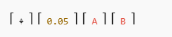
Example of a Feature Control Frame:
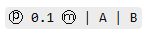
Interpretation: The position of the hole must be within a 0.1 mm diameter tolerance zone, considering Maximum Material Condition (MMC), with respect to Datum A and Datum B.
4. GD&T Tolerance Zones: Defining Acceptable Variations
Unlike traditional tolerances, which define linear limits, GD&T tolerance zones are geometric.
Example: A cylinder’s roundness must be within a 0.05 mm cylindrical zone to rotate smoothly in an assembly.
5. Material Condition Modifiers: Improving Machining Flexibility
GD&T allows tolerance adjustments based on material conditions, helping optimize manufacturing costs and reduce scrap rates.
Example: If a hole is larger than the minimum required size, GD&T allows a looser tolerance zone to reduce machining costs.
6. Inspection and Quality Control Using GD&T
GD&T makes part inspection and verification easier by providing precise measurement criteria.
Example: A True Position tolerance of 0.1 mm means that the feature must fall within a circular measurement zone of 0.1 mm diameter during inspection.
Conclusion
GD&T is a powerful tool that ensures precision, clear communication, and cost-effective manufacturing. By defining tolerances geometrically instead of linearly, GD&T allows greater flexibility, reduces production costs, and improves assembly fit.
At VMT CNC Machining, we apply GD&T-compliant manufacturing techniques to deliver high-performance CNC machined parts with strict quality control.
Need precision CNC parts with GD&T tolerances? Contact us for expert machining solutions!
GD&T symbols are categorized into four main types:
This guide breaks down each GD&T symbol, its meaning, and how it applies to CNC machining.
Form Tolerance Symbols
Form tolerances control the shape and integrity of features without reference to a datum. These tolerances ensure that a feature maintains a specific geometric shape.
1. Straightness (⊥)
2. Flatness (⏥)
3. Roundness (◯)
4. Cylindricity (⌭)
Profile Tolerance Symbols
Profile tolerances control the contour of surfaces to ensure precise shapes in CNC machining.
5. Line Profile Tolerance (∩)
6. Plane Profile Tolerance (⌒)
Orientation Tolerance Symbols
Orientation tolerances control the angular relationship between features relative to a datum.
7. Parallelism (∥)
8. Perpendicularity (⊥)
9. Angularity (∠)
Position Tolerance Symbols
Position tolerances control the exact location of features to ensure proper fit and assembly.
10. True Position (ⓟ)
11. Coaxiality (⌖)
12. Concentricity (◎)
13. Symmetry (⌯)
Runout Tolerance Symbols
Runout tolerances control the variation of a feature when it rotates.
14. Circular Runout (⌰)
15. Total Runout (⌙)
Conclusion
GD&T symbols enhance precision, improve part functionality, and ensure proper fitment in CNC machining and engineering. By using standardized GD&T tolerances, manufacturers can reduce errors, improve efficiency, and ensure high-quality production.
At VMT CNC Machining, we apply GD&T-compliant techniques to ensure accurate and reliable CNC-machined parts. Whether you need tight tolerance machining or expert GD&T application, we provide high-performance solutions for aerospace, automotive, medical, and industrial components.
Need precision CNC machining with GD&T-defined tolerances? Contact us today for expert consultation and high-quality manufacturing!
Beyond the basic GD&T symbols, there are several advanced tolerancing concepts and related symbols that enhance manufacturing precision. These symbols and features help control complex part geometries and ensure interchangeability in CNC machining. Understanding these related GD&T symbols can improve design intent, reduce errors, and optimize production efficiency.
Envelope Requirements (⧄)
Free State of Nonrigid Parts (⧅)
Application of Minimum Material Condition (LMC) (⦵)
Application of Maximum Material Condition (MMC) (⦶)
Indication of Projected Tolerance Zones (⦷)
No Material Requirements (⦹)
Indication of Tangent Planes (ASME Only)
Non-Uniform Profile Tolerance (ASME Only)
Tolerance Features
Datum Indication (A, B, C)
Datum Target (⦸)
Theoretical Exact Dimension (TED)
Common Tolerance Zones
Profile Tolerance (Perimeter)
Profile Tolerance (Overall)
Moveable Datum Target (ASME Only; Recommended for ISO)
Countersinking (ASME Only)
Statistical Tolerance (ASME Only)
Other Advanced GD&T Features
Free State
Independence Requirements
Minimum Material Conditions (LMC)
Maximum Material Condition (MMC)
Unequal Bilaterals
Conclusion
Understanding these advanced GD&T symbols is essential for high-precision CNC machining. By implementing these tolerance features, manufacturers can improve accuracy, reduce assembly issues, and optimize production efficiency.
Need precision CNC machining with GD&T tolerances? Contact VMT today!
A tolerance zone in Geometric Dimensioning and Tolerancing (GD&T) defines the permissible variation in a part's geometry. It ensures that machined components fit and function properly within an assembly. Tolerance zones apply to features such as radii, diameters, and surface profiles, guiding manufacturers in achieving consistent and precise part production.
In CNC machining, defining tolerance zones correctly helps reduce manufacturing errors, ensure part interchangeability, and improve assembly efficiency.
Control Radius (CR) in Tolerance Zones
Key Features of Control Radius:
Spherical Diameter Tolerance Zone (⌀)
Key Features of Spherical Diameter Tolerance Zone:
Spherical Radius Tolerance Zone (SR)
Key Features of Spherical Radius Tolerance Zone:
Diameter Tolerance Zone (⌀)
Key Features of Diameter Tolerance Zone:
Conclusion
Understanding tolerance zones such as Control Radius, Spherical Diameter, Spherical Radius, and Diameter is critical for precision CNC machining and GD&T applications. These tolerances ensure proper function, improve manufacturing consistency, and enhance part reliability in high-performance applications.
Looking for precision CNC machining with tight tolerance control? Contact VMT for expert machining solutions!
A Feature Control Frame (FCF) is a fundamental element of Geometric Dimensioning and Tolerancing (GD&T). It serves as a structured method to specify tolerances, datums, and geometric controls for a part's features. The FCF communicates critical information to machinists, quality inspectors, and engineers, ensuring parts meet precise design specifications.
In CNC machining, the Feature Control Frame ensures parts are manufactured with consistency and accuracy, reducing errors and improving assembly efficiency.

What is a Feature Control Frame?
A standard Feature Control Frame consists of three primary sections:
Example of a Feature Control Frame:
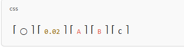
Interpretation: This example represents a true position tolerance of 0.02 mm, referenced from three datums (A, B, and C).
Components of a Feature Control Frame
1. Geometric Characteristic Symbol
The first section of the FCF contains the GD&T symbol that defines the type of control applied to the feature. Common symbols include:
⏤ Flatness
2. Tolerance Value
This section defines the maximum allowable variation from the ideal feature shape or position.
3. Material Condition Modifier (if applicable)
Material Condition Modifiers define the tolerance based on feature size:
4. Datum References
Example Applications of a Feature Control Frame
Flatness Tolerance Example:
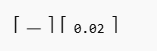
Meaning: The surface must remain within 0.02 mm of a perfectly flat plane.
True Position Tolerance Example:
Meaning: The hole or feature must be within 0.05 mm of its intended position, referenced from datums A and B.
Perpendicularity Tolerance Example:
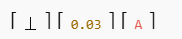
Meaning: The surface must remain within 0.03 mm of being perfectly perpendicular to datum A.
Why Use a Feature Control Frame in CNC Machining?
Conclusion
A Feature Control Frame (FCF) is a critical component of GD&T, providing clear tolerance specifications for CNC machining and manufacturing processes. It ensures consistent, high-quality parts that meet functional and design requirements. Proper use of FCFs improves efficiency, reduces waste, and enhances product reliability in various industries.
Need precise CNC machining with GD&T expertise? Contact VMT for high-accuracy parts today!
Precision and Efficiency in Manufacturing
Understanding Geometric Dimensioning and Tolerancing (GD&T) and Feature Control Frames (FCF) is essential for ensuring manufacturing accuracy, consistency, and efficiency. These tools provide clear, standardized instructions that allow machinists, engineers, and quality inspectors to maintain tight tolerances and ensure part interchangeability in complex assemblies.
Enhancing Quality and Reducing Costs
By applying GD&T principles and properly using Feature Control Frames, manufacturers can:
Why GD&T and FCFs Matter in CNC Machining
For industries such as aerospace, automotive, medical, and electronics, where precision is critical, GD&T and Feature Control Frames provide the necessary guidance to produce high-performance CNC machined parts. By eliminating ambiguity in engineering drawings, they ensure that each component meets exact specifications and functions as intended.
Partner with VMT for High-Precision CNC Machining
At VMT, we specialize in precision CNC machining with GD&T expertise to ensure every part meets the highest quality standards. Whether you need custom machining, prototype development, or large-scale production, our team has the experience and advanced equipment to deliver accurate, reliable, and cost-effective parts.
Looking for expert CNC machining services with precise GD&T applications? Contact VMT today for top-tier manufacturing solutions!

Why was concentricity removed from GD&T?
Concentricity was removed from ASME Y14.5-2018 because it was difficult to inspect and measure accurately using standard metrology tools. It has been replaced by position tolerance or runout tolerance, which provide a more practical and precise way to control feature alignment.
Why was symmetry removed from GD&T?
Symmetry was also removed in ASME Y14.5-2018 due to inspection challenges. Instead, position tolerance and profile tolerance are preferred, as they offer better control over feature alignment and are easier to measure.
What is the free state symbol in GD&T?
The free state symbol (F) indicates that a feature must be measured without external forces applied, ensuring the part maintains its designed shape when not restrained. This is critical for thin-walled and flexible components.
Which GD&T symbol does not require a datum?
Form tolerances such as flatness, straightness, circularity (roundness), and cylindricity do not require a datum reference, as they control the shape of a feature independent of other features.
Can we give position tolerances without using a datum?
Yes, position tolerance can be applied without a datum if it controls a feature relative to itself or a set of similar features. However, for functional assemblies, position tolerance is often referenced from datums.
What are the 14 symbols in GD&T?
The 14 fundamental GD&T symbols are:
Does flatness require a datum?
No, flatness does not require a datum because it controls a surface’s overall form without reference to another feature.
Does perpendicularity require a datum?
Yes, perpendicularity typically requires a datum because it controls the orientation of a feature relative to another feature or surface.
What does flatness 0.1 mean?
Flatness 0.1 means that all points on the specified surface must lie within a tolerance zone of 0.1 mm. The surface cannot deviate more than 0.1 mm from a perfectly flat plane.
Can a curved surface be a datum?
Yes, a curved surface can be a datum if it serves as a functional reference for locating other features. Examples include cylindrical and spherical surfaces used in shafts and bearings.
Does straightness require a datum?
No, straightness is an independent tolerance and does not require a datum. It controls the form of a single line element.
What is the difference between a plane and a curved surface?
A plane is a flat surface with no curvature, while a curved surface has continuous variation in shape, such as cylinders, spheres, and cones.
Can a cylinder be a datum?
Yes, a cylindrical feature can be used as a datum. It is common in cases where parts need accurate rotational alignment, such as shafts and bores.
Can a datum be a hole?
Yes, a hole can be used as a datum when it serves as a primary locating feature for an assembly, such as in pin and dowel alignments.
Is the datum an ellipsoid?
No, a datum is not inherently an ellipsoid, but elliptical features can be used as datums if necessary for accurate positioning or alignment.
What is the symbol for flatness?
The symbol for flatness is ⏤, represented as a straight line in a feature control frame.
When to use LMC?
LMC (Least Material Condition) is used when a feature's smallest size or thinnest wall is functionally critical, such as in minimum clearance applications.
What is RMB in GD&T?
RMB (Regardless of Material Boundary) means the datum feature is measured as-is, regardless of material variations.
How to calculate GD&T tolerances?
GD&T tolerances are calculated using feature control frames, tolerance zones, and material condition modifiers. Tools like CMM (Coordinate Measuring Machines) and calipers help measure GD&T tolerances.
What is DRF in GD&T?
DRF (Datum Reference Frame) is the coordinate system created using datums, helping establish a standard reference for measurement.
What is CR in GD&T?
CR (Circular Runout) controls how much a circular feature can deviate when rotated around a datum axis.
What is Rule 1 in GD&T?
Rule #1 states that a feature of size must conform to its form controls at Maximum Material Condition (MMC). This means the actual size of a part must always fit within its tolerance zone.
Why use MMC?
MMC (Maximum Material Condition) ensures functional clearance and fitment between mating parts, optimizing manufacturing costs and part interchangeability.
How to calculate tolerance?
Tolerance = Maximum Limit - Minimum Limit
For GD&T, the tolerance is typically given in the feature control frame, ensuring that parts conform to functional requirements.
Conclusion
GD&T and Feature Control Frames (FCFs) play a crucial role in ensuring precision, consistency, and quality in CNC machining. By understanding tolerance principles, datum referencing, and feature control, manufacturers can reduce errors, improve assembly, and enhance cost-efficiency.
Looking for precision CNC machining services with expert GD&T application? Contact VMT today for high-quality custom machining solutions!

 +86 15099911516


 Read more