16 years one-stop China custom CNC machining parts factory

Hey there I’m VMT Sam!
With 25 years of CNC machining experience we are committed to helping clients overcome 10000 complex part-processing challenges all to contribute to a better life through intelligent manufacturing. Contact us now
 0 |
Published by VMT at Oct 30 2026 | Reading Time:About 6 minutes


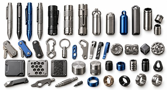
Successful custom CNC EDC parts production depends on more than achieving tight machining tolerances. Material selection, wall thickness, thread and moving clearances, surface-treatment allowances, cosmetic requirements, and inspection methods must be planned together from the design stage. When these factors are controlled through DFM, precision CNC machining, and prototype validation, manufacturers can achieve smoother assembly, more consistent finishes, lower scrap rates, and a reliable transition from prototypes to mass production.
Everyday Carry (EDC) gear has evolved from simple utility tools into high-precision, custom accessories where craftsmanship meets functionality. From sourcing the satisfying click of a custom bolt-action pen, the buttery-smooth action of a titanium knife pivot, to the weather-resistant seal of a compact pill case, you will demand perfection in both aesthetics and mechanical performance.
In this guide, we will break down everything you need to know: from identifying key EDC product categories and selecting the right materials, surface treatment recommendations, manufacturing challenges and solutions, to mastering DFM (Design for Manufacturability) guidelines and transitioning smoothly from prototype to mass production.
At the end, we share a case study: by implementing a 0.03mm thread pitch offset, custom pie-jaw expansion fixtures, optimized deep-cavity tooling, and internal anodizing racking plugs, our team solved custom EDC pill cases’ wall distortion and post-coating binding, delivering smooth M16x1.0 thread engagement within +/-0.015mm wall tolerance and slashing the scrap rate from 26% down to 0.7%.
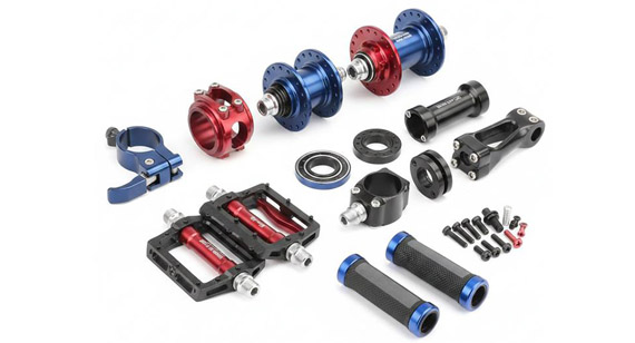
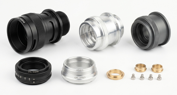
Custom CNC machined EDC (Everyday Carry) parts are precision, non-standard components produced by computer-controlled machine tools that remove material from solid metal or engineering plastic stock according to a custom design. Precision CNC machining is one of the suitable manufacturing methods to produce custom EDC components. By utilizing precision milling, turning, and multi-axis machining, the factory will meet your satified requirements like ±0.005mm to ±0.01mm tight tolerances, intricate internal geometries, and surface finishes with cosmetic details that mass-stamped or cast parts simply cannot replicate. Custom CNC machining touches almost every corner of the EDC industry, and here is a breakdown of the most popular examples:
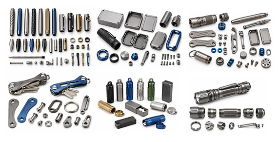
Because EDC gear is subjected to daily wear, sweat, friction, and impact, material properties like strength, hardness, corrosion resistance are what you should trade-off. Another important factor is that you should consider the comsumers experiences like the colors or textures they like or not, the price fit or not with production cost consideration, etc. Below lists the most popular materials with what you may concern for you to choose the fit materials:
| Material | Popular Grades | Key Features and Why Choose It? |
| Titanium | Grade 5, Grade 23 | Advanced Metal of EDC. Very high strength-to-weight ratio, corrosion-resistant, anodizable into vibrant colors, but expensive. Ideal for high-end knife scales, pens, and flashlights. |
| Aluminum | 6061-T6, 7075-T6 | Lightweight and Versatile. Cost-effective, easy to machine, perfect for complex shapes and anodizing. Ideal for common EDC parts with friendly cost and cosmetic surface. |
| Brass and Copper | C360 Brass, Tellurium Copper | Premium Weight and Patina. Relatively heavy, distinctive feel that develops a unique patina over time. Great for custom flashlight bezels, pens, and fidget gear. |
| Stainless Steel | 303, 304, 316L | Durable and Wear-Resistant. Excellent toughness, scratch resistance, and good corrosion resistance. Frequently used for pocket clips, pivot hardware, and rugged containers. |
| Plastics and Composites | Delrin (POM), Carbon Fiber | Smooth and Lightweight. Delrin offers low friction for sliders and internal sleeves; Carbon Fiber provides high rigidity and modern high-tech aesthetics. |
Reviewing these 7 critical design features early ensures your custom EDC parts achieve optimal tactile feedback, tight assembly fit, and lower unit costs, without costly tool re-engineering:
Tool Access and Internal Geometries
Deep internal pockets, square inside corners, and narrow slots limit cutting tool reach and require ultra-small end mills. But small radius end mills vibrate easily, leading to poor surface finish or broken tools.
Therefore, you should check whether the CNC machining services supplier has multi-axis CNC machines (such as 5-axis milling) or sinker EDM capability. They will also proactively suggest you minor internal corner radius adjustments (for example, changing a sharp internal corner to R >= 1.5mm) to allow tooling and speed up cycle times.
Wall Thickness and Structural Stability
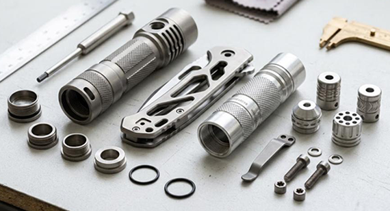
Thin-walled structures (like flashlight tube housings or skeletonized knife handles) are vulnerable to chatter, heat deformation, and clamping distortion during high-speed machining.
Evaluate if the factory understands material stress relief and customized soft-jaw fixture design. Recommended minimum wall thickness limits by material include:
Datums and Tolerance Stack-Up
Multi-part EDC assemblies (such as multi-piece pens or folding knife pivots) rely on precise alignment across multiple features. Over-tolerancing every dimension increases scrap rates, while under-tolerancing leads to loose or misaligned parts.
Ensure your engineering drawing clearly defines key reference datums, shoulders, and critical hole centers. Ask the supplier: "How will your quality team manage tolerance stack-up during final assembly to guarantee a smooth fit?"
Threaded and Moving Interfaces
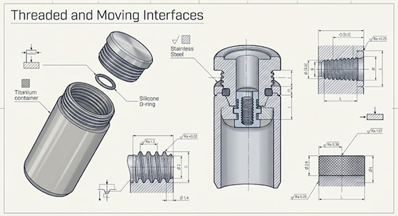
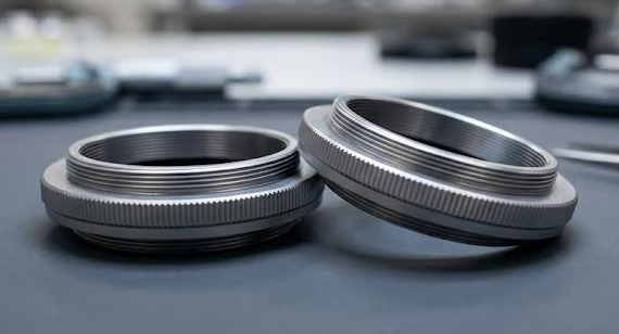
Fine pitch threads on titanium or stainless steel EDC containers are prone to galling if pitch diameter, pitch tolerance, and deburring are not correctly engineered.
Verify that the supplier accounts for thread clearance before applying surface treatments like anodizing or PVD coatings. The manufacturer should test threaded caps and sliding interfaces using functional gauge plugs or master matching components during production.
Surface Finish Allowance
Post-processing operations (like hard-coat anodizing, PVD, or heavy bead blasting) change part dimensions by adding or removing material layers, which can alter final fits. You should clarify on engineering prints whether critical dimensions represent pre-plate or post-plate sizes. The CNC partner will program offset adjustments during initial machining so that final parts remain strictly within drawing tolerances after finishing.
Burr-Sensitive and Cosmetic Zones
EDC products are interactive consumer goods that people hold, flip, and carry daily. Sharp edges, micro-burrs in narrow slots, or visible cutter marks destroy the premium user experience.
Inspect the supplier's deburring and edge-break process (for example, vapor honing, tumbling, or precision hand deburring under microscopes). Confirm that cosmetic surfaces are clearly marked on drawings so clamping marks are hidden in non-visible areas.
Inspection Channel and Quality Control Plan
Intricate internal features or micro-threads must be measurable. Features that cannot be measured cannot be reliably controlled in mass production.
Audit the supplier's Quality Control Process. Ensure they have CMM (Coordinate Measuring Machines), optical profile projectors, and specialized thread gauges tailored for micro EDC hardware.
The assembly is important in custom precision EDC production because mechanical action and haptic feedback define the user experience. Minor dimensional deviations or improper clearance planning can cause mechanism binding, thread seizing, or loose play. These following practical solutions can help you avoid common assembly issues for EDC production:
| Assembly Defect | Primary Cause | Actionable Solution |
| Binding/Gritty Sliding Action | Missing running clearance, misaligned datums, or guide rail offset. | • Set 0.02mm – 0.05mm running clearance. • Keep parallelism within 0.01mm. • Add internal relief grooves to trap micro-debris. |
| Galling/Thread Seizing | Dry friction on identical metals (Titanium/Stainless) or sharp crests. | • Use stub ACME or rounded threads. • Add 0.03mm – 0.05mm pitch allowance for coatings. • Specify deburring on thread lead-ins. |
| Loose Play/Excessive Wobble | Uncontrolled tolerance stack-up or oversized pin holes. | • Use a single primary datum shoulder. • Add spring washers or adjustable pivots for pre-load. • Use H7/g6 tolerances on pivot pins and sleeves. |
| Coating Scraping/Premature Wear | Sharp contact edges gouging soft anodizing/PVD layers. | • Apply edge radii (R >= 0.3mm) on contacting edges. • Reserve 10um – 25um clearance per side for plating. • Design non-contact relief zones on cosmetic faces. |
Surface finishing does far more than dictate the visual appeal of an custom CNC machining EDC product. Processes like anodizing, PVD coating, bead blasting, and polishing will alter surface dimensions, sharp edge clarity, and tactile friction. Failing to plan finishes leads to fit failures, stripped threads, and unexpected rework costs.
Dimensional Growth and Clearance Offsets: Anodizing and physical vapor deposition (PVD) add microscopic material layers. For example, hard-coat anodizing (Type III) typically adds 10um to 25um of thickness per surface, reducing internal thread pitch diameters and narrowing sliding tracks. This is what machining partners will mention you to note and they can then apply negative offsets during CNC milling to ensure final dimensions meet tight tolerances after coating.
Impact on Thread Pitch and Mating Clearances: Plating builds up unevenly on thread crests and sharp corners, causing fine-pitch threads on titanium pill cases or flashlight tubes to bind or seize during assembly. This is usually what machining partners to reserve an additional 0.03mm to 0.05mm clearance allowance on thread pitch diameters. But you should specify masking on critical internal threads if functional thread engagement takes priority over cosmetic color coverage.
Edge Crispness and Tactile Feel: Abrasive blasting, tumble deburring, and heavy polishing dull fine chamfers, knurling textures, and sharp corner definitions. Over-blasting can erode delicate laser engravings and micro-machined patterns. You can define cosmetic and non-cosmetic surfaces clearly on engineering prints. The factory will then select media grit sizes (such as glass bead vs ceramic bead) early, and set strict radius limits for deburring passes to preserve tactile ergonomics.
Surface Treatment Compatibility with Custom EDC Components
| Finishing Process | Material Compatibility | Typical Thickness Change | Functional Advantage |
| Anodizing (Type II / III) | Aluminum | Type II: +5um to 15um Type III: +10um to 25um |
Wear resistance, vibrant color customization, and corrosion protection. |
| PVD Coating | Titanium, Stainless Steel | +1um to 5um | High surface hardness, scratch resistance, and premium metallic hues. |
| Passivation and Electropolishing | Stainless Steel Alloys | Minimal material removal (-1um) | Removes free iron particles to prevent rust without altering fit tolerances. |
| Bead Blasting and Stonewashing | Titanium, Aluminum, Brass | Minimal surface erosion | Hides daily handling scratches and provides a matte, non-reflective grip texture. |
| Micro-Arc Oxidation (MAO / PEO) | Aluminum, Titanium | +5um to 20um | Creates an ultra-hard ceramic-like surface with exceptional wear, heat, and corrosion resistance. |
| Cerakote (Thin-Film Ceramic Coating) | Titanium, Aluminum, Stainless Steel, Brass | +6um to 13um | Superior chemical and abrasion resistance with endless solid color choices and high-durability finish. |
| DLC (Diamond-Like Carbon) Coating | Titanium, Stainless Steel | +1um to 3um | High surface hardness (near diamond levels), ultra-low friction coefficient, and deep stealth black aesthetics. |
| Chemical Patina / Antiquing | Brass, Copper, Bronze | Minimal surface layer change | Accelerates natural aging to create a unique vintage look without affecting machining dimensions. |
| Vapor Honing / Liquid Honing | Aluminum, Titanium, Stainless Steel | Negligible surface erosion | Provides a velvet-smooth satin texture that is finer and less aggressive than traditional dry bead blasting. |
A functional prototype is not only a visual showpiece, but also a base for roduction viability. Before approving full-scale manufacturing, evaluate your custom EDC prototypes against this 5-point verification checklist:
Tactile Ergonomics and Edge Feel
Assembly Seal and Structural Tightness
Movement and Haptic Feedback
Surface Coating Integrity
Zero-Rework Functional Pass
Overcoming custom EDC pill cases’ wall distortion and post-coating binding, delivering smooth M16x1.0 thread engagement within +/-0.015mm wall tolerance and slashing the scrap rate from 26% down to 0.7%.
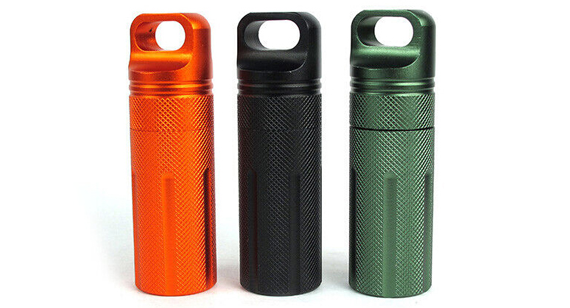
A client approached us with a custom EDC project: a precision 6061 aluminum pill case featuring a separate threaded lid, deep internal cavity, thin 1.0mm exterior walls, and a high-cosmetic anodized finish.
The functional specs are smooth M16x1.0 thread engagement without binding, strict concentricity of +/-0.01mm between the neck and deep cavity, and a flawless Type II color anodized surface with zero visible clamping marks.
The client’s previous machining vendor failed during initial batch production.
Our engineering team conducted a thorough failure analysis and identified causes propably be: the previous vendor machined threads to nominal print sizes without reserving anodizing growth allowances, used rigid three-jaw chucks that deformed the thin walls during cutting, and failed to protect cosmetic faces during surface treatment.
The challenge was not one isolated tolerance. Thread engagement, lid alignment, wall stability and finishing allowance all needed to remain compatible after machining and surface treatment.
To solve this, our team implemented a comprehensive strategy:
As a result, all of finished assemblies achieved smooth, hand-tight thread engagement and seamless lid-to-body alignment without binding or play. Wall thickness remained uniform within +/-0.015mm tolerance across all production runs, and scrap rates dropped from 26% down to 0.7%.
High-precision custom CNC EDC parts production requires balancing premium aesthetics, tactile performance, and tight tolerances with cost-effective production. By selecting the right materials, addressing structural DFM features early, planning for surface treatment offsets, and establishing clear inspection criteria, your team can reliably turn complex 3D models into market-ready EDC gear.
Final Two Key Takeaways to Keep in Mind:
Facing challenges with material selection, surface finishing choices, assembly fits, or cosmetic texture details for your custom EDC design? Welcome to contact our engineering team to receive a comprehensive DFM analysis and a fast quote for your custom CNC EDC parts. [ We support 2D Drawings (PDF files), 3D Drawings (IGS/STP/STEP files)].
Send your 2D drawings, 3D CAD models, material, tolerance requirements, thread specifications, surface finish, cosmetic requirements, prototype quantity and production quantity. VMT will review material selection, DFM, CNC machining, thread and assembly fit, surface finishing, inspection and quotation requirements.
All information and uploaded files are secure and confidential.
1 Tell us what you need
2 Get solution & quote
3 Approve production
Email: inquiry@vimetal.com.cn
Q1: What is the MOQ for custom CNC EDC parts, and how much do prototype and mass production costs differ?
A:Most CNC machine shops support short-run prototyping from 1 to 10 pieces. Prototyping carries a higher unit price due to upfront CAD/CAM programming, custom soft-jaw fixture setup, and machine calibration costs. When transitioning to mass production of 100+ units, unit costs typically decrease by 40% to 60% through fixture reuse and optimized toolpaths.
Q2: How do aluminum vs titanium differ in lead times and tooling costs for EDC parts?
A:Aluminum cuts quickly with low tool wear, offering the shortest lead times and lower costs. Titanium have poor thermal conductivity and work-harden easily, requiring slower cutting speeds and frequent tool changes, which typically doubles or triples machining time compared to aluminum, and the machining cost can be higher.
Q3: How do you ensure batch-to-batch color and texture consistency for high-end titanium flashlight parts?
A:Consistency depends on strict bath chemistry control and uniform surface pre-treatment (such as blast pressure and media grit). We will seal a "Best Sample" during the initial production run. For subsequent batches, we standardizes media grit, anodizing voltage, racking methods, and dip times to match the approved sample before shipment.
Q4: If a EDC design includes components like screws, springs, or bearings, can the you provide pre-assembly?
A:Yes. We offer supply chain integration and pre-assembly services. You simply list the standard hardware specifications (such as ceramic bearings, O-rings, or Torx screws) in your BOM. After completing machining and surface finishing, we will perform 100% haptic feel testing and delivers fully assembled products.
Q5: Why do ultra-narrow anti-slip grooves or deep micro-textures significantly increase EDC part costs?
A:Micro-features (such as grooves under 1.0mm wide) require extremely thin micro end mills. These tools operate at slow feed rates, take light cuts, and break easily, requiring high-rpm spindles and multiple light passes that significantly increase machine runtime, which also means higher machining cost.
Q6: What is the most frequently overlooked detail on 2D drawings for custom EDC parts?
A:The most common oversight is failing to clarify whether dimensions apply before or after surface finishing (pre-plate vs post-plate sizes), along with omitting acceptable racking and clamping locations on cosmetic faces. Specifying these details prevents post-coating fit binding and reduces unnecessary cosmetic scrap.
The technical information and manufacturing advice shared on the VMT website are for general guidance only. While we strive for accuracy, VMT does not guarantee that the processes, tolerances, or material properties mentioned are applicable to every specific project. Any reliance you place on such information is strictly at your own risk. It is the buyer's responsibility to provide definitive engineering specifications for any production orders. Final specifications and service terms shall be subject to the formal contract or quotation confirmed by both parties.


 +86 15099911516




 Read more