16 years one-stop China custom CNC machining parts factory

Hey there I’m VMT Sam!
With 25 years of CNC machining experience we are committed to helping clients overcome 10000 complex part-processing challenges all to contribute to a better life through intelligent manufacturing. Contact us now
 13340 |
Published by VMT at Aug 25 2026 | Reading Time:About 8 minutes
13340 |
Published by VMT at Aug 25 2026 | Reading Time:About 8 minutes


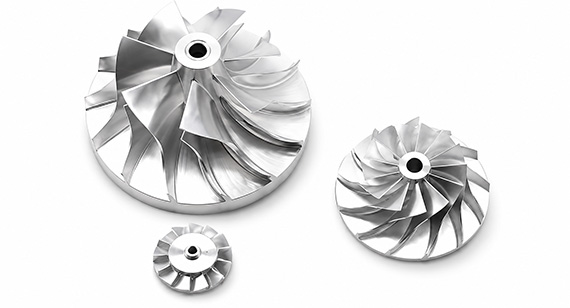
Estimating CNC machining time with only cutting length and feed rate can underestimate the real production cycle. Tool changes, rapid moves, probing, multiple setups, inspection, and part handling all add time. If these factors are ignored, your cost and delivery estimate may be inaccurate. A structured cycle-time calculation helps you plan production more realistically.
CNC machining time is basically calculated as cutting length divided by feed rate. For turning, T = L / (f × N). For milling, feed rate = N × Z × fz and machining time = toolpath length / feed rate. Actual CNC cycle time also includes non-cutting movements and auxiliary operations.
Below, you will see how CNC turning, milling, and drilling time are calculated, why theoretical cutting time differs from actual cycle time, and how to estimate machining time more accurately from your part drawing.
There are many types of CNC machining operations, and each one may require a slightly different calculation method. However, the basic principle is simple:
Machining Time = Cutting Length ÷ Feed Rate
For operations such as CNC turning or drilling where feed is specified per revolution:
T = L / (f × N)
Where:
| Symbol |
Meaning |
Typical Unit |
| T |
Machining time | min |
| L |
Cutting length | mm |
| f |
Feed per revolution | mm/rev |
| N |
Spindle speedre | v/min |
| V |
Cutting speed | m/min |
| D | Workpiece or tool diameter | mm |
Spindle speed can be estimated using:
N = (1000 × V) / (π × D)
These formulas calculate the theoretical cutting time. In actual CNC production, however, the machine spends additional time on movements and operations that do not directly remove material.
A more practical way to understand CNC cycle time is:
CNC Cycle Time = Cutting Time + Rapid Movement Time + Tool Change Time + Probing Time + Other Machine Operations
If you are estimating production time and cost per part, setup time may also need to be allocated across the production quantity:
Effective Time per Part = CNC Cycle Time + Setup Time ÷ Batch Quantity
For example, a cutting operation may theoretically require only two minutes. Once tool changes, positioning, probing, part handling, and other operations are included, the actual production cycle may be several minutes longer.
Tip: Use the basic machining-time formula for an initial estimate. For quotation and production planning, evaluate the complete machining process rather than cutting time alone.
CNC machining distance or length divided by speed or rate is the most basic rule. According to different process characteristics, the general formula for the time of multiple processes such as turning, milling and end face is as follows:
The basic method for calculating CNC machining time is to divide the cutting distance by the programmed feed rate.
However, the exact formula depends on the machining process.
CNC turning commonly uses feed per revolution. CNC milling often uses feed per tooth, number of cutting edges, and spindle speed. Drilling may require additional consideration of hole depth, approach distance, peck cycles, and retract movements.
This is why one universal formula cannot accurately represent every CNC machining operation.
For simple features, manual formulas provide a useful estimate. For complex parts with many tools, setups, or 3D toolpaths, CAM simulation and actual machine-cycle data are usually more reliable.
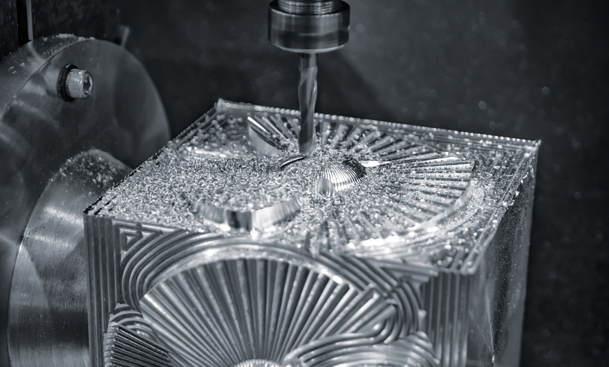
CNC cutting time, machining time, cycle time, setup time, and lead time are closely related, but they do not mean exactly the same thing.
| Term |
What It Usually Means |
| Cutting Time |
Time when the cutting tool is actively removing material |
| Machining Time |
Time required for the machining operations used to produce the part |
| CNC Cycle Time |
Cutting plus programmed machine movements and auxiliary operations required to complete one cycle |
| Setup Time |
Fixture preparation, tooling, offsets, program verification, and first-piece setup |
|
Production Time per Part |
Cycle time plus applicable handling and allocated setup or batch-related time |
| Lead Time |
Material preparation, setup, machining, finishing, inspection, production scheduling, packaging, and other order processes |
For example, a CNC milling toolpath may contain three minutes of actual cutting. The machine may also need probing, several tool changes, rapid positioning, and other programmed movements before the part is complete.
For this reason, cutting time should not be treated as the complete production time when you estimate CNC machining cost or manufacturing capacity.
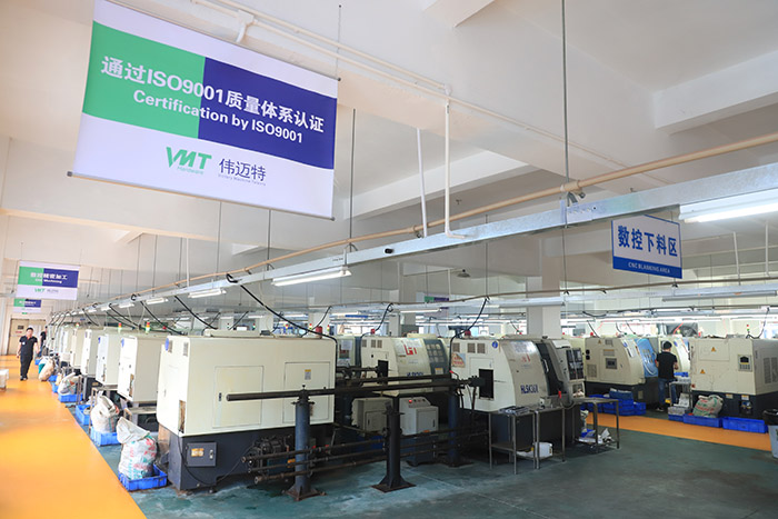
Turning is the process of producing turned parts on a lathe with a single-point tool. When calculating or estimating the CNC machining cycle time of the turning process, the formula is also based on T=L/feed*N, L or length=(tool approach + working length + tool overtravel)*No. In the pass, N refers to the average RPM, which is equal to 1000*cutting speed/π*average diameter.
CNC turning removes material while the workpiece rotates and the cutting tool follows a programmed path.
For a basic turning operation:
T = L / (f × N)
Where:
The total cutting length may include:
L = Tool Approach + Working Length + Tool Overtravel
If several passes are required, each pass must be included in the calculation.
Spindle speed can be estimated using:
N = (1000 × Cutting Speed) / (π × Diameter)
For simple cylindrical turning, this gives a useful estimate. For parts with multiple diameters, grooves, tapers, threads, bores, or changing cutting parameters, it is better to calculate the major operations separately.
CNC Turning Cycle Time Calculation Example
Assume the following turning conditions:
| Parameter |
Example Value |
| Cutting Length |
100 mm |
| Spindle Speed |
1,500 RPM |
| Feed per Revolution |
0.20 mm/rev |
| Number of Passes |
2 |
First calculate the feed rate:
Feed Rate = 1,500 × 0.20 = 300 mm/min
The cutting time for one pass is:
100 ÷ 300 = 0.333 min
For two passes:
0.333 × 2 = 0.666 min
The theoretical turning time is therefore approximately:
0.67 minutes, or about 40 seconds
This is only the theoretical cutting time.
A complete CNC turning cycle may also include:
For a simple shaft, the difference between cutting time and actual cycle time may be relatively small. For a complex turned component using several tools, the difference can be much greater.
What If the Turning Diameter Changes?
Turning calculations become more complex when the machining diameter changes significantly or the program uses constant surface speed.
A stepped shaft, for example, may require different RPM values at different diameters. Grooves, threads, bores, and finishing operations can also use different cutting parameters.
For preliminary estimation, calculate each major turning operation separately.
For accurate batch-production planning, CAM simulation and actual machine-cycle verification are more dependable than using one average formula for the entire component.
Note: Increasing feed or spindle speed only to reduce calculated cycle time can create other problems. Thread quality, dimensional accuracy, surface roughness, chip control, tool life, and process stability must still meet your drawing requirements.
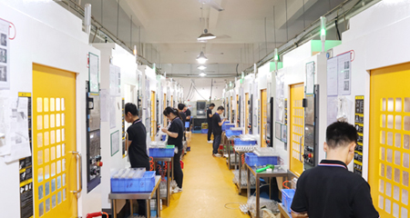
CNC milling is a machining technology that can process various cross-section grooves or ribs, vertical, horizontal and inclined planes, rotary surfaces, spiral grooves, etc. For milling operations, the feed rate may be in units per tooth, which means you need to know the number of cutting edges, teeth, or grooves on the tool. According to L=working length+tool approach+tool overtravel+forced distance, f=feed per revolution=feed per tooth*number of teeth, N=1000*cutting speed/π*D, enter the formula T=L/f* N calculates the milling time.
CNC milling can produce pockets, slots, holes, ribs, flat surfaces, contours, inclined surfaces, and complex 3D geometry.
For milling, feed rate is commonly calculated from spindle speed, number of cutting edges, and feed per tooth:
Feed Rate = N × Z × fz
Where:
Once the feed rate is known:
Milling Time = Cutting Toolpath Length ÷ Feed Rate
The important point is that the cutting length should be based on the actual toolpath rather than only the external dimensions of your part.
CNC Milling Machining Time Calculation Example
Assume:
| Parameter | Example Value |
| Spindle Speed | 4,000 RPM |
| Number of Flutes | 4 |
| Feed per Tooth | 0.05 mm/tooth |
| Cutting Toolpath Length | 400 mm |
First calculate feed rate:
4,000 × 4 × 0.05 = 800 mm/min
Then calculate cutting time:
400 ÷ 800 = 0.5 min
The theoretical milling time is therefore:
0.5 minutes, or 30 seconds
However, this does not mean the complete CNC milling cycle requires only 30 seconds.
Your program may also contain:
Deep pockets, thin walls, small internal radii, complex 3D surfaces, tight tolerances, and demanding surface-finish requirements can also require additional toolpaths.
This is why two CNC milled parts with similar external dimensions can have very different machining times.
Basic CNC drilling time can be estimated using drilling travel, spindle speed, and feed per revolution.
For a simple drilling operation:
Drilling Time per Hole = Drilling Travel / (Feed per Revolution × RPM)
For several identical holes:
Basic Drilling Time = Time per Hole × Number of Holes
However, hole depth alone does not determine the complete drilling cycle.
| Drilling Factor | Effect on Machining Time |
| Peck Drilling | Adds repeated feed and retract movements |
| Spot Drilling | Adds another tool and machining operation |
| Reaming | Adds a precision finishing process |
| Counterboring | Requires additional cutting travel |
| Countersinking | Adds another machining operation |
| Chip Evacuation | May require additional retracts |
| Hole Probing | Adds verification time |
| Tool Changes | Add non-cutting machine time |
For shallow holes in easy-to-machine materials, theoretical and actual drilling time may be relatively close.
For deep holes or difficult-to-machine materials, heat control, chip evacuation, hole accuracy, and tool life may substantially increase the actual cycle time.
A machining-time formula assumes that the cutting tool travels over a known distance at a defined feed rate.
A real CNC machine performs many additional actions when the tool is not removing material.
Rapid Positioning
The cutting tool must move between features, approach the workpiece, and retract to safe positions.
These movements do not remove material, but they still consume machine time.
Tool Changes
Your part may require separate roughing cutters, finishing cutters, drills, taps, boring tools, chamfer cutters, or probes.
Each automatic tool change adds time.
A few seconds may appear insignificant for one prototype, but the accumulated effect can become important when thousands of parts are produced.
Tool Approach and Retract
Toolpaths normally include safe approach, lead-in, lead-out, and retract movements.
Simply measuring the finished feature length therefore does not always represent the complete programmed travel.
Workpiece Probing
Precision CNC machining may use probes to establish work offsets, locate the workpiece, or verify important features during machining.
Probing can improve process control and reduce scrap risk, but it also adds cycle time.
Multiple Setups
Some parts cannot be completely machined from one clamping orientation.
The workpiece may need to be repositioned or transferred to another fixture.
Additional setups increase:
For suitable complex parts, 5-axis CNC machining can sometimes reduce the number of setups by providing access to more surfaces in a single clamping.
In-Process Inspection
Critical bores, hole positions, flatness, concentricity, threads, or mating dimensions may require verification before machining continues.
This additional time can be necessary to maintain stable production quality.
Chip Control
Deep pockets, narrow slots, deep holes, and difficult materials may require chip-clearing movements.
Poor chip evacuation can damage the cutting tool, workpiece, or finished surface, so machining time cannot always be reduced simply by increasing feed rate.
Machine Acceleration and Deceleration
A programmed feed rate of 1,000 mm/min does not mean that every movement occurs continuously at exactly 1,000 mm/min.
The CNC machine must accelerate, decelerate, and change direction.
Short toolpath segments and complex contours may therefore achieve a lower average feed rate than the programmed value.
Tip: Manual formulas are useful for preliminary estimation. For complex CNC parts, CAM toolpath simulation combined with actual machine data gives a more realistic production estimate.
Even when two parts have similar external dimensions, their machining times can be very different.
Part Geometry
Geometry has a major influence on CNC machining time.
Features that can increase machining time include:
These features may require additional tools, smaller cutting depths, slower feeds, or more machining setups.
Material
Different materials allow different cutting speeds, feeds, depths of cut, and tooling strategies.
Aluminum can generally be machined faster than many stainless steels, titanium alloys, or nickel-based alloys.
However, machining time also depends on the exact alloy, cutting tool, machine rigidity, feature geometry, tolerance, and required surface quality.
Tolerance
A standard-tolerance feature may be machined efficiently in one or two operations.
A critical bore, flat surface, hole position, concentric feature, or precision mating interface may require:
Applying unnecessarily tight tolerances to non-critical dimensions can therefore increase both machining time and manufacturing cost.
Surface Roughness
Roughing toolpaths are designed to remove material efficiently.
A fine sealing, mating, optical, or cosmetic surface may require additional finishing passes, smaller step-over, lighter cutting loads, and more stable machining conditions.
Number of Tools
More machining operations normally require more tools.
Every additional tool may add:
Workholding and Number of Setups
A part that can be machined in one or two setups may be more efficient than a similar component requiring several re-clamping operations.
Fixture design influences loading speed, rigidity, tool accessibility, datum consistency, and production repeatability.
Batch Quantity
Setup time has a much greater cost impact on one prototype than on hundreds or thousands of parts.
For example, if setup requires 120 minutes:
For 1 part:
120 min setup per part
For 100 parts:
120 ÷ 100 = 1.2 min setup allocation per part
For 1,000 parts:
120 ÷ 1,000 = 0.12 min setup allocation per part
This is one reason prototype unit prices are often significantly higher than production unit prices.
If you only have a 2D drawing and 3D CAD model, the most practical method is to break your component into individual manufacturing operations.
1. Identify the Machining Process
Determine whether your part requires:
2. Determine the Required Setups
Review how many orientations are required to access all features while maintaining the specified datums and tolerances.
A design that requires four setups will usually take longer than one that can be completed in one or two setups.
3. Review Stock Size and Material Removal
Compare the raw stock dimensions with the finished geometry.
A part requiring extensive material removal will usually need more roughing time than a near-net-shape component.
4. Separate Roughing and Finishing Operations
Identify:
Each operation may use different tools and cutting parameters.
5. Estimate Each Toolpath
For each major operation, estimate:
6. Add Non-Cutting Time
Do not forget:
7. Consider Setup Time
For quotation purposes, setup time should be considered relative to the production quantity.
8. Validate the Estimate
For complex parts or larger production runs, CAM simulation or prototype machining can be used to confirm the initial estimate.
Two aluminum parts measuring 100 × 100 × 30 mm can have completely different machining times.
One may be a simple plate.
The other may include:
Therefore, external dimensions alone cannot accurately predict CNC machining time.
A CNC machining time calculator can provide a quick preliminary estimate before detailed CAM programming.
CNC Turning Calculator Inputs
A basic CNC turning calculator can use:
The calculator can then estimate:
CNC Milling Calculator Inputs
For CNC milling, useful inputs include:
The calculator can estimate:
CNC Drilling Calculator Inputs
For drilling:
can be used to calculate a basic drilling estimate.
However, a simple machining-time calculator normally does not understand your complete manufacturing process.
It may not include:
Rapid Moves + Tool Changes + Probing + Multiple Setups + Inspection + Loading/Unloading + Auxiliary Operations
For this reason, calculator results should be treated as a preliminary estimate rather than a guaranteed production cycle time.
You can also build a simple CNC machining time calculator in Excel.
CNC Turning Cycle Time Calculation Formula in Excel
Assume:
| Cell | Input |
| B2 | Cutting Length |
| B3 | RPM |
| B4 | Feed per Revolution |
Use:
=B2/(B3*B4)
If:
the result is theoretical cutting time in minutes.
If several passes use the same parameters, you can multiply the result by the number of passes.
CNC Milling Machining Time Calculation in Excel
Assume:
| Cell | Input |
| B2 | Toolpath Length |
| B3 | RPM |
| B4 | Number of Flutes |
| B5 | Feed per Tooth |
Use:
=B2/(B3*B4*B5)
You can then add additional Excel columns for:
This allows you to separate theoretical cutting time from estimated production cycle time.
CNC machining time has a direct relationship with machine capacity, production cost, and delivery planning.
A simplified cost relationship can be expressed as:
Machining Cost ≈ Machine Time × Machine Hourly Rate + Setup + Tooling + Inspection + Secondary Operations
This is why cycle-time optimization becomes increasingly important as production quantity increases.
Assume process optimization reduces the CNC cycle from eight minutes to six minutes.
For one prototype, the two-minute difference may have limited cost impact.
For 5,000 parts:
2 min × 5,000 = 10,000 min
This equals approximately:
166.7 machine hours
The effect can therefore become significant during batch production.
However, reducing cycle time should not compromise:
The best machining process is not simply the fastest process.
It should balance:
Cycle Time + Cost + Quality + Repeatability + Production Risk
Cycle-time optimization should begin with the entire manufacturing process rather than simply increasing RPM or feed rate.
Reduce Unnecessary Setups
Better fixture planning can reduce part re-clamping and repeated alignment.
For suitable geometries, multi-axis or 5-axis machining may allow more features to be completed in one setup.
Optimize Toolpaths
CAM programming can reduce unnecessary rapid moves, air cutting, inefficient retracts, and repeated tool movements.
Select Appropriate Cutting Tools
The correct tool geometry, coating, diameter, and cutting parameters can improve material removal efficiency while maintaining tool life.
Combine Operations Where Practical
Some drilling, chamfering, turning, or milling operations can sometimes be combined or reorganized to reduce tool changes and handling.
Improve Fixture Loading
For batch production, fixture design can significantly affect loading and unloading time.
Multi-part fixtures may improve machine utilization when they are appropriate for the geometry and tolerance requirements.
Use DFM to Remove Unnecessary Machining
DFM review can identify design details that add machining time without improving part function.
Examples include:
For larger production quantities, even a small reduction in cycle time can have a measurable effect on machine capacity and unit cost.
Note: Any cycle-time reduction should still be validated against your dimensional accuracy, surface finish, burr requirements, tool life, and assembly needs.
When you request a CNC machining quotation, calculating cutting length and feed rate alone is not enough to determine the real production time of your part.
VMT reviews your drawing and manufacturing requirements before selecting the machining strategy.
Drawing and DFM Review
Your 2D drawing and 3D CAD model are reviewed for:
Potential manufacturing risks can be identified before production begins.
Process Selection
Depending on your part geometry, the manufacturing route may use:
Selecting the correct process can reduce unnecessary setups and improve machining efficiency.
Fixture and Setup Planning
Fixture design affects both machining time and dimensional stability.
Reducing unnecessary re-clamping can help improve datum consistency, shorten handling time, and reduce accumulated positioning error.
Machining Sequence Planning
The machining sequence may include:
Roughing → Semi-Finishing → Finishing → Drilling → Tapping → Boring → Threading → Chamfering
The sequence is planned according to geometry, rigidity, tolerance, and surface requirements rather than only machining speed.
Cutting Parameter Review
Feeds and speeds are selected according to:
A faster programmed feed is not always a better manufacturing solution.
In-Process and Final Inspection
Critical dimensions may require in-process measurement, gauges, CMM inspection, or other verification.
Inspection requirements should be considered when planning actual production capacity.
Prototype Validation
For complex parts or larger production quantities, prototype machining can provide real cycle-time data.
The process can then be adjusted before batch production through fixture optimization, toolpath improvement, machining sequence changes, or cutting-parameter refinement.
The objective is not only to calculate how many minutes a cutting tool moves.
It is to develop a stable manufacturing process that helps you control machining time, dimensional quality, production cost, and delivery risk.
A CNC machining time formula is useful for preliminary planning, but your actual manufacturing time depends on part geometry, material, tolerances, machining strategy, setup requirements, inspection, surface requirements, and production quantity.
If you are preparing a prototype or production project, send VMT your 2D drawing and 3D CAD model.
We can review your:
Upload your 2D/3D drawings to request a CNC machining quote and DFM feedback for your project.
Send your 2D drawing, 3D CAD model, material, tolerances, surface-finish requirements, prototype quantity and production quantity. VMT will review the machining process, setups, tooling, cycle-time risks, inspection requirements and potential cost improvements.
All information and uploaded files are secure and confidential.
1 Tell us what you need
2 Get solution & quote
3 Approve production
Email: inquiry@vimetal.com.cn
What is the CNC cycle time calculation formula?
For basic cutting, machining time is calculated by dividing cutting length by feed rate. For turning operations where feed is specified per revolution, the formula is T = L / (f × N). Actual CNC cycle time can also include rapid movements, tool changes, probing, and other machine operations.
How do you calculate cycle time in a CNC machine?
Calculate the cutting time for each machining operation first. Then add relevant non-cutting movements such as rapid positioning, tool changes, probing, indexing, and other programmed operations. For production planning, loading, unloading, setup allocation, and inspection may also need to be considered.
How do you calculate CNC turning cycle time?
Basic CNC turning time is calculated using cutting length, feed per revolution, and spindle RPM. If several passes or tools are required, calculate the machining time of each operation and add the appropriate non-cutting time.
What is the CNC turning time formula?
A common theoretical formula is:
T = L / (f × N)
where:
How do you calculate CNC milling time?
First calculate the milling feed rate:
Feed Rate = RPM × Number of Flutes × Feed per Tooth
Then:
Milling Time = Toolpath Length ÷ Feed Rate
The complete production cycle should also consider tool changes, rapid moves, probing, and other operations.
What is the difference between machining time and CNC cycle time?
Machining time normally refers to the time required to perform machining operations. CNC cycle time may include additional programmed machine movements such as rapid positioning, tool changes, probing, indexing, and auxiliary operations.
Does CNC setup time count as cycle time?
Setup time is normally evaluated separately from the repeating CNC machine cycle. Setup may include fixture preparation, tooling, offsets, program verification, and first-piece preparation. For cost estimation, setup time can be divided across the production quantity.
Why is actual CNC machining time longer than calculated cutting time?
A basic formula normally calculates tool movement at a defined feed rate. Actual machining may also include rapid movements, tool changes, probing, chip clearing, acceleration and deceleration, multiple setups, inspection, and part handling.
Can CNC machining time be calculated in Excel?
Yes. Basic turning and milling formulas can be entered into Excel. Additional columns can also be added for setup, tool changes, probing, loading, inspection, and production quantity.
Can you estimate CNC machining time from a drawing?
Yes, but overall part dimensions alone are not enough. A reliable estimate should also consider material, stock size, geometry, tolerances, setups, tool access, cutting operations, surface requirements, inspection, and production quantity.
How can CNC machining cycle time be reduced?
Cycle time can sometimes be reduced through fixture optimization, fewer setups, better CAM toolpaths, appropriate tooling, optimized feeds and speeds, combined operations, and more efficient part loading. Any optimization should still maintain tolerance, surface quality, burr control, tool life, and process stability.


 +86 15099911516





 Read more