16 years one-stop China custom CNC machining parts factory

Hey there I’m VMT Sam!
With 25 years of CNC machining experience we are committed to helping clients overcome 10000 complex part-processing challenges all to contribute to a better life through intelligent manufacturing. Contact us now
 292 |
Published by VMT at Dec 16 2021
292 |
Published by VMT at Dec 16 2021


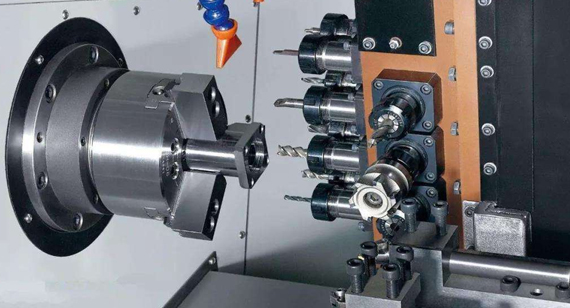
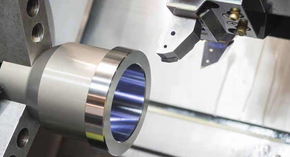
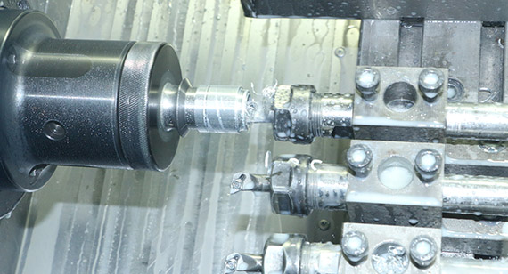
When precision CNC turning parts and CNC turning crankshaft parts, due to the complex shape of the crankshaft and the longer crank arm, the extension length of the turning tool should be longer. Due to the long overhang length of the turning tool, the rigidity of the tool holder is easily deteriorated, coupled with the impact load during cutting, resulting in low rigidity of the process system and prone to vibration and deformation. Therefore, it is necessary to try to improve the crankshaft and cutters in the CNC turning process. rigidity.
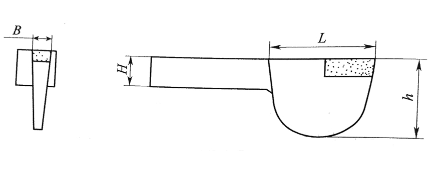
1. Throat-shaped turning tool.
The protruding part of the turning tool is shaped like a fish belly, which not only ensures that the crank does not collide with the tool holder when the crank rotates, but also improves the rigidity of the protruding part of the tool body. The height h of fish maw is generally (0.6~0.8)L, and the height H of the clamping part of the knife body should be as large as possible.
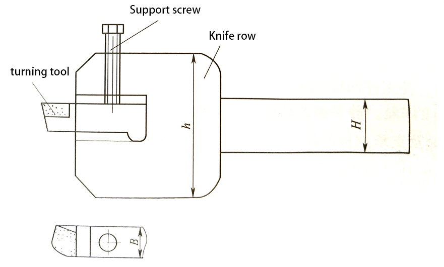
2. Line turning tool
The turning tool is composed of a high-rigidity tool row and a tool head, and the tool head is fastened with screws. This structure is more convenient for sharpening and changing tools, saving the material of the tool body, but when precision CNC turning parts, when CNC turning rigid parts, chip evacuation is not smooth, and it is easy to squeeze into the gap at the front end of the tool body during cutting. Tool head and tool row. Observing the processing conditions is wrong, so it is mostly used for roughing.
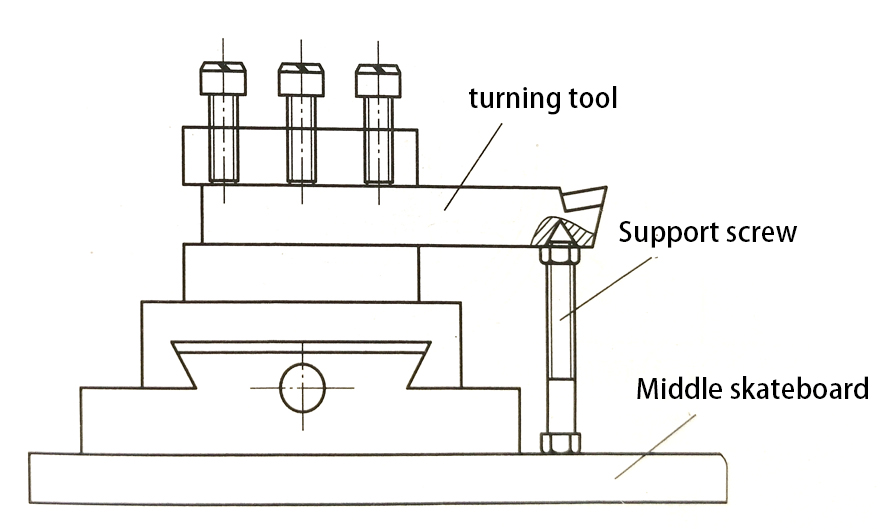
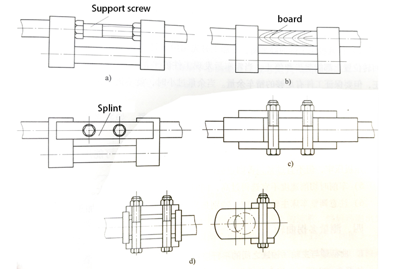
3. Auxiliary support for turning tool
A screw hole is pre-processed at the bottom of the turning head, and the screw is supported on the middle sliding plate. The support length is adjusted and locked with a nut to improve the rigidity of the turning tool during rough machining. When this method is adopted, the rotation of the tool post is inconvenient.
4. Auxiliary support for turning tools
A screw hole is pre-processed at the bottom of the turning head, and the screw is supported on the middle sliding plate. The support length is adjusted and locked with a nut to improve the rigidity of the turning tool during rough machining. When this method is adopted, the rotation of the tool post is inconvenient.
5. When CNC machining the rotor journal, the shaft must be adjusted
Make it coincide with the rotation center of the spindle of the CNC machining lathe. Therefore, the most important process requirement in mass production is to use reasonable fixtures and clamping methods to ensure the accuracy of eccentricity.
6. The center hole and eccentric center hole at both ends are used as a reference for CNC machining
At present, according to the accuracy requirements of the crankshaft itself, the batch size and the specific requirements of the existing CNC machining equipment level, various CNC machining methods can be selected. For example, the main journal can use traditional CNC turning technology and advanced CNC machining technology, such as lathes and high-speed CNC milling, to improve the efficiency and quality of CNC machining.
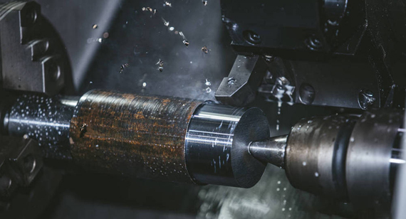
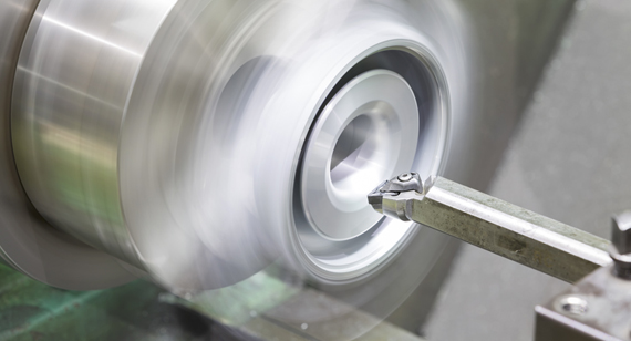
When precision CNC turning crankshaft parts, due to the complex shape of the crankshaft and the longer crank arm, the extension length of the turning tool should be longer. Due to the longer overhang length of the turning tool, the stiffness of the tool holder is likely to deteriorate, and the impact load during cutting results in low rigidity of the process system and prone to vibration and deformation. Therefore, it is necessary to try to improve the crankshaft and the tool during CNC machining. The stiffness.
The rough machining and finishing of the main journal and the end of the large crankshaft are carried out on a lathe. First, the crankshaft journals near the end are processed, and then the shafts with these journals are installed on the hub, and then other journals are processed by CNC. Such a sub-sequence can eliminate the deformation of the central axis. At the same time, we need to deal with all the surfaces where the rotation axis coincides with the main neck axis: the end face, contour and bevel of the cheek. The small crankshaft journal is processed by a double-sided or centrally driven multi-tool lathe.
The machined intermediate or extreme journals are mounted on the turntable or special chuck. At that time, some or all of the main journals and the end surfaces of the cheeks that were not clamped were CNC turning.

 +86 15099911516


 Read more