16 years one-stop China custom CNC machining parts factory

Hey there I’m VMT Sam!
With 25 years of CNC machining experience we are committed to helping clients overcome 10000 complex part-processing challenges all to contribute to a better life through intelligent manufacturing. Contact us now
 363 |
Published by VMT at Aug 11 2026 | Reading Time:About 8 minutes
363 |
Published by VMT at Aug 11 2026 | Reading Time:About 8 minutes


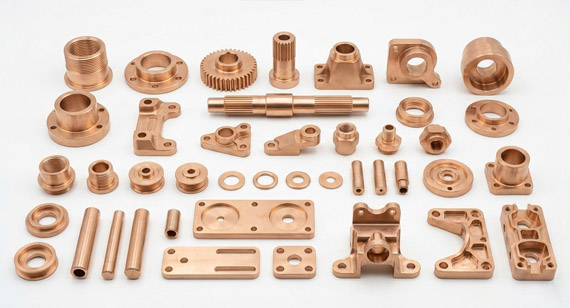
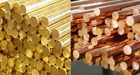
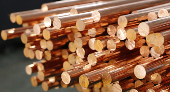
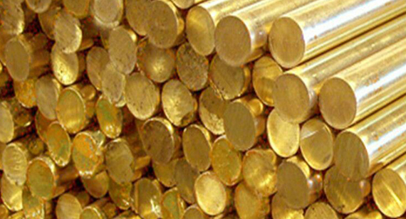
Copper CNC machining is essential for producing high-precision components that demand superior thermal and electrical conductivity. From EV power electronics and 5G telecommunications to medical devices, copper and its alloys remain the top choice for critical engineering parts so as to increasing the needs of copper machining services. But machining copper presents unique challenges—such as work hardening, gummy chips, and edge burrs; and perhaps you are troubling with these issues for your copper CNC machined parts now.
This comprehensive guide covers the properties, common copper grades, machining techniques, and practical solutions to help you optimize your precision copper parts production. At the end, we will also share a case study of how we helped our client with their copper heat sink surface burr issues.
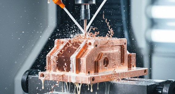
Copper machining refers to the process of shaping copper and its alloys into precise and intricate parts using various types of CNC machines and cutting tools.
Unlike conventional machining methods, Copper CNC Machining employs advanced CNC lathes and milling machines equipped with specialized tools designed to handle the unique properties of copper. These methods( copper CNC turning, and copper CNC milling) ensure high accuracy, smooth surface finishes, and the ability to produce complex geometries that are difficult to achieve with traditional machining techniques.
Copper machining is integral in producing components for electrical applications, heat exchangers, aerospace parts, and medical devices, where the copper's exceptionally thermally and electrically conductivity, ductile and corrosion-resistant characteristics are the priority. The precision and efficiency offered by copper CNC machining make it an indispensable process in modern manufacturing, enabling the production of copper machined parts that meet rigorous industry standards.
Then, how about the different copper and it’s alloy grades?
Table: Copper Grades & its Alloy Comparison
Choosing the right copper grade is critical for balancing part performance and manufacturing cost. Pure copper offers maximum conductivity, while alloyed copper improves machinability and mechanical strength.
| Feature | Oxygen-Free Copper | ETP Copper | Tellurium Copper | Beryllium Copper | Free-Cutting Brass |
| Material Grade | C10100 / C10200 | C11000 | C14500 | C17200 | C36000 (copper-zinc alloy; machinability baseline) |
| Content of Copper Element (Cu %) | ≥ 99.99% | ≥ 99.90% | ~ 99.5% (0.4–0.7% Te) | ~ 98.0% (1.8–2.0% Be) | 57.0–60.0% (Rem. Zn, 2.5–3.7% Pb) |
| Machinability Rating | 20% | 20% | 85% | 20% (annealed) | 100% (Standard Baseline) |
| Electrical Conductivity (% IACS) | 101% | 100% | 93% | 22–28% | 26% |
| Primary Advantage | Highest purity, excellent thermal/electrical conductivity, no hydrogen embrittlement | High conductivity, ductile, universal electrical copper grade | Free-machining copper, excellent chip breaking, dramatically reduces tool wear | Exceptional mechanical strength, high fatigue resistance, non-magnetic | Excellent machinability, low tool wear, smooth surface finish, cost-effective |
| Limitations | Soft and gummy; poor machinability; prone to burrs and tool adhesion | Susceptible to hydrogen embrittlement at high temperatures; low machinability | Slightly lower conductivity than pure copper; higher raw material cost | Toxic dust hazard during dry machining/grinding; low electrical conductivity; high cost | Significantly lower electrical/thermal conductivity; contains lead (RoHS limitations) |
| Typical Applications | Vacuum electronics, semiconductors, audio conductors | Electrical busbars, switchgear, transformer components | High-volume CNC turnings, welding torch tips, electrical connectors | Precision springs, aerospace bushings, injection mold inserts | Fasteners, fittings, fluid power components, hardware |
Selecting the right process and cutting tools is critical to overcoming copper's natural ductility and high thermal conductivity.
Key Copper Machining Processes
Tool Selection & Cutting Strategies for Copper
Using generic tooling on copper often results in heavy burrs, poor surface finish, and tool failure due to material adhesion or hardness. Follow these engineered tooling guidelines tailored to specific copper grades:
| Tool Parameter | C10100 / C10200 | C11000 | C14500 | C17200 | Engineering Reason |
| Tool Material | Micro-grain Carbide / PCD | Micro-grain Carbide | Uncoated Carbide / HSS | Coated Solid Carbide | Micro-grain carbide maintains ultra-sharp edges to shear soft copper or resist abrasive wear in alloys. |
| Rake Angle | High Positive (15° – 20°) | High Positive (12° – 15°) | Moderate Positive (10° – 15°) | Neutral to Slight Positive (5° – 10°) | Sharp positive angles shear soft pure copper to prevent pushing/burrs, while tougher alloys need stronger edge support. |
| Flute Design | Polished 2-Flute / 3-Flute | Polished 2-Flute / 3-Flute | Standard 2-Flute or 3-Flute | 3-Flute or 4-Flute | Mirror-polished flutes prevent gummy copper chips from adhering; extra flutes enhance rigidity for hard alloys like C17200. |
| Tool Coating | DLC / TiB2 | DLC / TiN | Uncoated / TiN | TiAlN / AlCrN | DLC prevents Built-Up Edge (BUE) on pure copper (avoid AlTiN on C10100-C11000); high-heat resistance coatings suit tough C17200. |
| Coolant Strategy | High-pressure water-soluble coolant | High-pressure flood coolant | Flood coolant / MQL | Heavy flood coolant (Wet machining only) | High pressure flushes gummy chips instantly. Note: Wet machining C17200 prevents hazardous airborne toxic dust. |
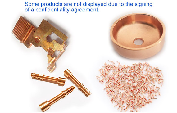
Copper machining is integral to a wide array of industries due to copper’s excellent electrical and thermal conductivity, durability, and versatility. The ability to produce high-precision, intricate components makes copper machining essential for applications that demand both functionality and reliability.
Achieving the desired surface finish is essential in copper machining, as it impacts both the aesthetic appeal and functional performance of the parts. Various surface finishing techniques are employed to enhance the appearance, corrosion resistance, and overall quality of CNC machining parts.
Media Blasting
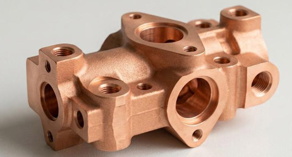
Media blasting involves propelling abrasive particles at high speeds to remove surface contaminants, roughen the surface, or create a uniform texture. This technique is used to clean and prepare copper parts for further finishing processes, ensuring that the surface is free of debris and defects. Media blasting can also be used to create specific surface textures that enhance the adhesion of coatings or improve the aesthetic appearance of the part.
Electroplating
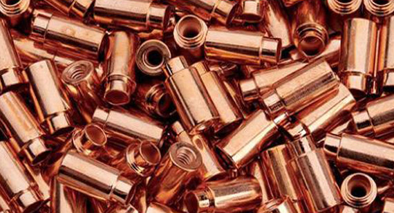
Electroplating is a process that involves depositing a thin layer of metal onto the surface of a copper part through an electrochemical reaction. This technique is used to enhance the corrosion resistance, wear resistance, and aesthetic appeal of the machined parts. Common electroplating metals used with copper include nickel, chromium, and gold, each providing different surface properties tailored to specific applications.
Electropolishing
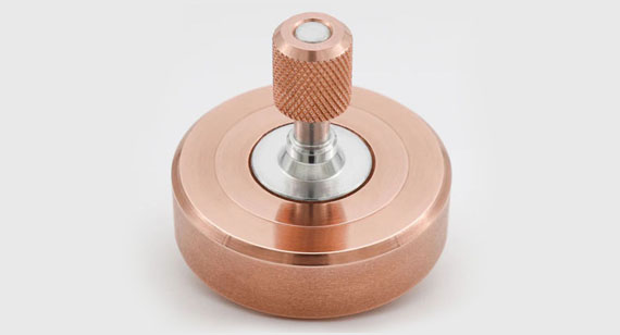
Electropolishing is a chemical process that removes a thin layer of material from the surface of a copper part, resulting in a smooth and shiny finish. This technique enhances the aesthetic appearance of the part and improves its corrosion resistance by eliminating surface imperfections and reducing the likelihood of microbial growth. Electropolishing is commonly used in medical devices, electronics, and decorative applications where a high-quality surface finish is essential.
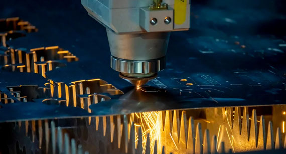
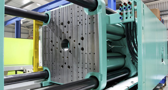
While CNC machining offers unmatched precision for complex 3D copper parts, alternative manufacturing processes may be more cost-effective depending on your part geometry, wall thickness, and production volume:
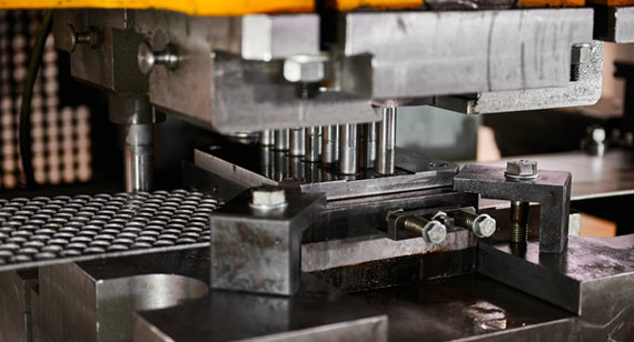
Fiber Laser Cutting
Metal Injection Molding (MIM)
Cold Heading / Forging

Optimizing your part design for manufacturability (DFM) is the most effective way to ensure high dimensional accuracy while minimizing overall production costs. When designing copper components, focus on these critical factors:
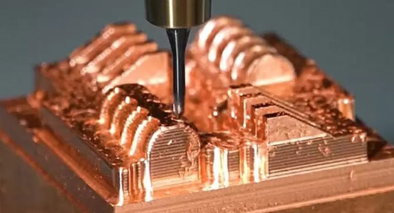
Material Selection & Machinability Impact
Radius & Internal Cavity Design
Realistic Tolerances & Wall Thickness
Simplified Threading & Undercuts
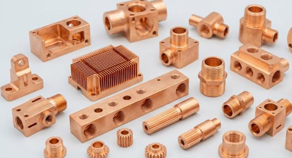
VMT Precision Machining Services specializes in Copper CNC Machining, offering a comprehensive range of services tailored to meet the unique needs of various industries. With state-of-the-art CNC machines, advanced tooling systems, and a team of experienced technicians, VMT Precision Machining delivers high-quality CNC machining parts made from copper and copper alloys. Our expertise in handling different copper grades and alloys ensures that we can produce precise, durable, and reliable components for applications in electronics, aerospace, medical devices, automotive, and more. Whether you require custom CNC machining, prototype machining, or high-volume production, VMT Precision Machining provides efficient and cost-effective solutions to meet your manufacturing requirements. Our commitment to quality, precision, and customer satisfaction makes us a trusted partner for all your copper machining needs.
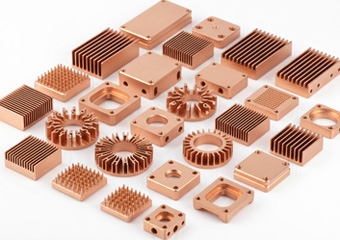
A medical equipment manufacturer approached our engineering team with a challenge involving a high-density C10100 oxygen-free copper heat sink. The part required ultra-fine micro-channels and flat mating surfaces for thermal contact.
However, their previous supplier faced severe edge burrs and tool adhesion (BUE), resulting in a 25% defect rate during final quality inspection.
To overcome the soft and gummy nature of pure C10100 copper, our engineering team redesigned the machining process:
By optimizing the cutting tool and machining methods, we removed secondary manual deburring, improved surface roughness from Ra 1.6 to Ra 0.8, and reduced the client's scrap rate to zero. Production cycle time was cut by 18%, allowing the customer to scale up their assembly line ahead of schedule.
Several factors drive the adoption and growth of Copper CNC Machining, including the increasing demand for high-performance electrical components, advancements in CNC technology, and the material’s inherent machinability and recyclability. Compared to traditional machining methods, Copper CNC Machining offers numerous advantages such as enhanced precision, reduced cycle times, excellent surface finishes, and the ability to produce complex geometries efficiently. While Copper CNC Machining presents challenges such as work hardening and tool wear, implementing best practices and using high-quality tools can mitigate these issues, ensuring consistent machining performance and high-quality outcomes.
Need Help with Complex Copper Components? Whether you are dealing with tight tolerances, surface burrs, or challenging alloy selections, our engineering team is ready to optimize your design for manufacturability. Upload your drawing today for an instant quote and free DFM review! [2D Drawings (PDF files), 3D Drawings (IGS/STP/STEP files)]
Send your drawings, requirements, and target quantity. VMT will review your project and provide a machining solution and quote.
All information and uploaded files are secure and confidential.
1 Tell us what you need
2 Get solution & quote
3 Approve production
Email: inquiry@vimetal.com.cn
How to prevent Built-Up Edge (BUE) and chip adhesion when machining pure copper?
Built-Up Edge occurs because soft, pure copper adheres to the tool's cutting edge rather than shearing cleanly. To prevent BUE, use carbide tools with high positive rake angles and mirror-polished chip flutes. Apply low-friction coatings such as DLC (Diamond-Like Carbon) or TiB2. Note: Avoid AlTiN coatings, as aluminum reacts with copper under high cutting temperatures, increasing tool adhesion.
How to minimize burr formation and part deformation during copper CNC machining?
Copper’s high malleability causes the material to push outward and deform rather than cut cleanly, leading to heavy edge burrs. The burr formation can be minimized by maintaining ultra-sharp tool edges, optimizing feed rates, and using high-pressure, water-soluble coolant. For high-precision parts, integrate advanced post-processing deburring methods such as electropolishing or thermal deburring.
How to avoid work hardening when cutting copper and its alloys?
Work hardening is caused by tool rubbing or hesitant tool entry, which localized strain-hardens the material surface and accelerates tool wear on subsequent passes. To avoid this, maintain a constant and positive feed rate so the cutting edge continuously cuts beneath the work-hardened layer. Never allow the tool to dwell in the cut.
What are the differences between common copper alloys (Alloy 101, 110, 122, 145, and 147)?
Each copper alloy contains specific micro-elements tailored for distinct applications:
How to ensure safety and compliance when machining copper alloys (e.g., Beryllium Copper C17200)?
Follow these key safety and regulatory guidelines:
What is the recommended cutting speed for machining copper?
Cutting speeds for copper vary by alloy grade and operation. For soft pure coppers (C10100/C11000), typical surface speeds range between 150 to 300 m/min (500–1000 SFM) with sharp carbide tooling to prevent material sticking. Free-machining coppers like Tellurium Copper (C14500) can run much faster, reaching 300 to 500+ m/min (1000–1600 SFM) on CNC turning centers.
Which alloying elements in copper best enhance high-speed machinability?
Elements such as Tellurium (Te), Sulfur (S), and Lead (Pb) significantly improve machinability by acting as internal chip breakers during cutting operations. For instance, adding 0.4–0.7% Tellurium to copper (C14500) increases its machinability rating from 20% to 85%, enabling high-speed CNC machining with clean chip evacuation and significantly reduced tool wear.
The technical information and manufacturing advice shared on the VMT website are for general guidance only. While we strive for accuracy, VMT does not guarantee that the processes, tolerances, or material properties mentioned are applicable to every specific project. Any reliance you place on such information is strictly at your own risk. It is the buyer's responsibility to provide definitive engineering specifications for any production orders. Final specifications and service terms shall be subject to the formal contract or quotation confirmed by both parties.


 +86 15099911516




 Read more