15 years one-stop China custom CNC machining parts factory
 1026 |
Published by VMT at Dec 02 2024 | Reading Time:About 10 minutes
In the world of CNC machining, creating precise and functional holes is a critical aspect that can make or break the quality of a part. However, engineers and manufacturers often grapple with selecting the right hole type for their specific application, leading to design inefficiencies and production challenges. This confusion not only hampers the manufacturing process but also affects the performance and durability of the final product. Fortunately, understanding the various CNC machining hole types and their applications can streamline manufacturing, improve part functionality, and reduce costs.
Different hole types in CNC machining—such as through holes, blind holes, tapped holes, and counterbores—play a vital role in parts manufacturing. Choosing the appropriate hole type ensures optimal part performance, manufacturing efficiency, and cost-effectiveness in CNC machining services.
To fully grasp how hole types influence CNC machining and parts manufacturing, it's essential to delve into the specifics of each hole feature, their machining processes, and applications. This comprehensive guide will explore 28 engineering hole types, their characteristics, and how to select the right one for your custom CNC machining project.
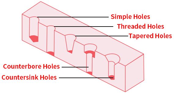
In machining, a hole feature refers to any cylindrical cavity created in a workpiece using various cutting tools and processes. Holes are fundamental elements in mechanical design and manufacturing, serving multiple functions such as accommodating fasteners, allowing fluid flow, or reducing weight. The characteristics of these holes—including their shape, size, depth, location, tolerance, surface finish, and additional features like chamfers—are crucial in determining the functionality and manufacturability of the part.
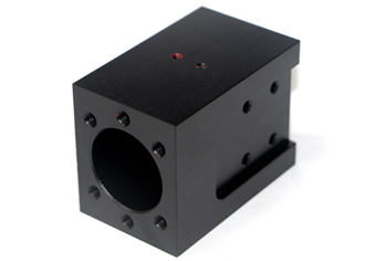
Hole Features
When designing holes in CNC machining parts, several features must be considered to ensure that the hole meets the intended function and can be manufactured efficiently. The main features of holes include:
Holes are fundamental features in parts manufacturing, serving various functions such as fastening, alignment, fluid flow, and weight reduction. In CNC machining, understanding the different hole types is essential for engineers and machinists to produce parts that meet specific design requirements and functional purposes. Below, we will examine each of the 28 engineering hole types, providing detailed insights into their definitions, standards, machining processes, and practical applications.
1. Simple Hole
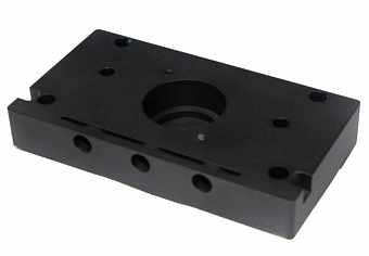
A simple hole is the most basic form of a hole in machining—a cylindrical cavity with a uniform diameter throughout its depth. It does not include any additional features like threads, countersinks, or counterbores. Simple holes are straightforward to produce and are often used in applications where complex features are unnecessary.
Conformity and Marking
Processing Technology and Machine Type
Application
Simple holes are ubiquitous in parts manufacturing due to their simplicity and ease of production. They serve various purposes, including:
2. Through Hole
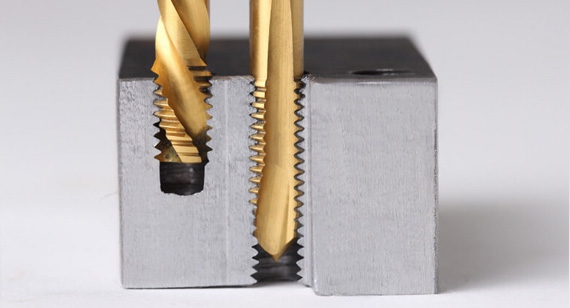
A through hole is a type of hole that extends entirely through a material, connecting one surface to the opposite surface. Unlike blind holes, through holes do not have a bottom within the material and allow objects or substances to pass completely through.
Conformity and Marking
Processing Technology and Machine Type
Application
Through holes are essential in various manufacturing scenarios:
3. Blind Hole
A blind hole is a hole that does not extend completely through the material; it stops at a specified depth within the workpiece. The bottom of a blind hole can be flat, angled, or rounded, depending on the design requirements.
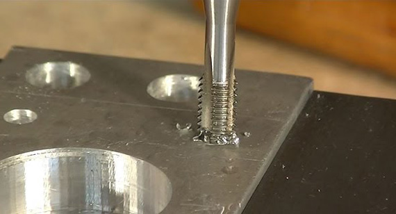
Conformity and Marking
Conformity: Blind holes require precise depth control, adhering to tolerances outlined in standards like ISO 2768 for general tolerances or specific design specifications.
Marking: Indicated on drawings by the diameter and depth, often using the depth symbol (⊥) (e.g., Ø12 mm ⊥ 30 mm deep).
Processing Technology and Machine Type
Application
Blind holes are utilized in various applications where penetrating the entire material is undesirable:
4. Tapered Hole
A tapered hole is a hole where the diameter decreases (or increases) progressively along its depth, forming a conical shape. The taper can be specified by an angle or a ratio between the diameter change and the depth.
Conformity and Marking
Processing Technology and Machine Type
Application
Tapered holes are essential in applications requiring secure, self-locking fits:
5. Tapped Holes
Tapped holes are holes that have internal threads cut into them, allowing threaded fasteners like screws or bolts to be inserted directly into the material without the need for a nut on the opposite side.
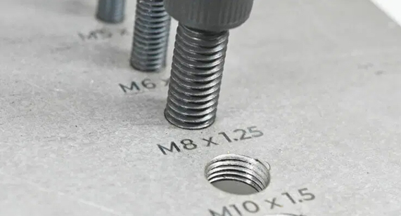
Conformity and Marking
Processing Technology and Machine Type
Application
Tapped holes are prevalent in nearly all industries due to their convenience and reliability:
6. Counterbore
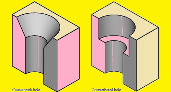
A counterbore is an enlarged, flat-bottomed cylindrical recess at the mouth of a hole, allowing the head of a socket head cap screw or bolt to sit flush with or below the surface of the material.
Conformity and Marking
Processing Technology and Machine Type
Application
Counterbores are critical in applications requiring smooth surfaces:
7. Countersink Hole
A countersink hole features a conical enlargement at the opening of a hole, designed to accommodate the head of a countersunk screw so that it sits flush with or below the surface.
Conformity and Marking
Processing Technology and Machine Type
Application
Countersink holes are widely used for:
8. Backdrill Hole
A backdrill hole involves drilling from the opposite side of a partially drilled hole to remove excess material or eliminate stubs in multi-layer printed circuit boards (PCBs).
Conformity and Marking
Processing Technology and Machine Type
Application
Backdrill holes are primarily used in:
9. Spotface Hole
A spotface hole is a shallow, flat-bottomed recess around a hole, providing a smooth and flat surface for a bolt head or washer to seat evenly.
Conformity and Marking
Processing Technology and Machine Type
Application
Spotface holes are used when:
10. Interrupted Holes
Interrupted holes are holes that intersect with another hole or cavity, resulting in a discontinuity along the hole's path. This can create challenges in machining due to varying cutting conditions.
Conformity and Marking
Processing Technology and Machine Type
Application
Interrupted holes are found in:
11. Threaded Clearance Holes
Threaded clearance holes are unthreaded holes that allow a threaded fastener to pass through without engaging threads, typically used in conjunction with a tapped hole on a mating part.
Conformity and Marking
Processing Technology and Machine Type
Application
Used in assembly processes where:
12. Reamed Holes
Reamed holes are holes that have been machined to a precise diameter and smooth finish using a reamer after initial drilling.
Conformity and Marking
Processing Technology and Machine Type
Application
Essential when:
13. Cross Holes
Cross holes are two or more holes that intersect at a common point or along a portion of their paths, forming a cross-shaped internal cavity.
Conformity and Marking
Processing Technology and Machine Type
Application
Common in:
14. Stepped Holes
Stepped holes have two or more diameters along their depth, creating a "step" profile inside the hole.
Conformity and Marking
Processing Technology and Machine Type
Application
Used for:
15. Gun Drilling Holes
Gun drilling holes are deep, small-diameter holes created using specialized gun drilling techniques that allow for accurate, straight holes with high length-to-diameter ratios.
Conformity and Marking
Processing Technology and Machine Type
Application
Essential in:
16. Ventilation Holes
A vent is a hole designed to allow air or gases to escape or enter a component, preventing pressure buildup or vacuum formation.
Conformity and Marking
Processing Technology and Machine Type
Application
Used in:
17. Guide Holes
A guide hole is a precisely located hole used to guide tools or components during assembly or machining processes.
Conformity and Marking
Processing Technology and Machine Type
Application
Critical in:
18. Screw Holes
A screw hole is a hole designed specifically for a screw, which may be threaded or unthreaded depending on the application.
Conformity and Marking
Processing Technology and Machine Type
Application
Common in all assemblies requiring screws for fastening.
19. Pin Hole
A pin hole accommodates a pin used for alignment, fastening, or rotation. Precision in diameter and location is essential.
Conformity and Marking
Processing Technology and Machine Type
Application
Used in:
20. Key Hole
A key hole is a slot or groove within a hole designed to accommodate a key, preventing rotation between connected parts.
Conformity and Marking
Processing Technology and Machine Type
Application
Essential in:
21. Polished Hole
A polished hole has an enhanced surface finish achieved through polishing processes, reducing friction and improving flow characteristics.
Conformity and Marking
Processing Technology and Machine Type
Application
Used in:
22. Micro Hole
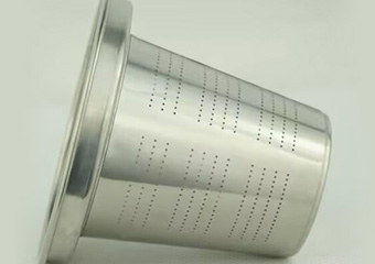
A micro hole is an extremely small hole, typically less than 1 mm in diameter, requiring specialized machining techniques.
Conformity and Marking
Processing Technology and Machine Type
Application
Found in:
23. Oil Hole
An oil hole allows lubrication to reach internal components, essential for reducing friction and wear.
Conformity and Marking
Processing Technology and Machine Type
Application
Used in:
24. Ejector Pin Hole
An ejector pin hole accommodates an ejector pin in molding processes, allowing parts to be pushed out of molds.
Conformity and Marking
Processing Technology and Machine Type
Application
Essential in:
25. Low Temperature Voids
Low temperature voids are holes or cavities created at low temperatures to prevent material deformation, often using cryogenic processes.
Conformity and Marking
Processing Technology and Machine Types
Application
Used in:
Conclusion
Understanding the various types of holes in CNC machining is vital for designing and manufacturing parts that meet specific functional requirements. Each hole type serves a unique purpose and requires particular machining processes and equipment. By selecting the appropriate hole types and employing the correct machining techniques, manufacturers can optimize part performance, reduce costs, and enhance production efficiency. Whether you're dealing with simple holes or complex geometries like key holes and micro holes, knowledge of these engineering hole types is essential in the field of CNC machining.
| Hole Type |
Purpose |
Shape |
| Simple Hole |
Basic passage or weight reduction |
Cylindrical |
| Through Hole |
Allows components or fasteners to pass through |
Cylindrical |
| Blind Hole |
Accommodates components without full penetration |
Cylindrical |
| Tapered Hole |
Fits tapered components securely |
Conical |
| Tapped Hole |
Receives threaded fasteners |
Cylindrical with threads |
| Counterbore |
Recesses bolt heads for a flush surface |
Cylindrical with flat bottom |
| Countersink Hole |
Recesses screw heads with angled surfaces |
Conical |
| Backdrill Hole | Removes excess material in PCBs |
Cylindrical |
| Spotface Hole |
Provides flat seating area on uneven surfaces |
Shallow cylindrical |
| Interrupted Hole |
Intersects with other holes or features |
Complex |
| Threaded Hole |
Internal threads for fasteners |
Cylindrical with threads |
| Threaded Clearance Hole |
Allows threaded fasteners to pass freely |
Cylindrical |
| Reamed Hole |
Precision fit with smooth finish |
Smooth cylindrical |
| Overlapping Hole |
Two holes partially overlapping |
Combined cylinders |
| Cross Hole |
Intersecting holes for complex pathways |
Intersecting cylinders |
| Stepped Hole |
Varying diameters along depth |
Cylindrical steps |
| Gun Drilling Hole |
Deep, small-diameter holes |
Long cylindrical |
| Ventilation Hole |
Allows air or gas flow |
Various shapes |
| Guide Hole | Guides tools or components during assembly |
Precision cylindrical |
| Screw Hole |
Designed for screws, may be threaded or not |
Cylindrical |
| Pin Hole |
Accommodates alignment or fastening pins |
Tight tolerance cylinder |
| Key Hole |
Houses keys to prevent rotation |
Slot or groove |
| Polished Hole |
Enhanced surface finish for reduced friction |
Smooth cylindrical |
| Micro Hole |
Extremely small holes for specialized uses |
Micro-scale cylindrical |
| Oil Hole |
Allows lubrication to internal components |
Small cylindrical |
| Ejector Pin Hole |
Houses ejector pins in molds |
Precision cylindrical |
| Low Temperature Void |
Created using cryogenic processes |
Various shapes |
Holemaking is a fundamental aspect of CNC machining, involving various processes tailored to specific hole types, materials, and precision requirements. Selecting the appropriate method ensures efficiency, accuracy, and cost-effectiveness in manufacturing.
CNC Milling
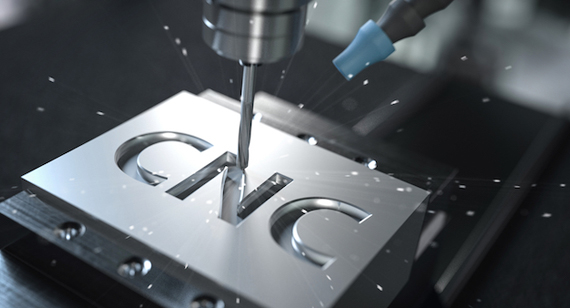
CNC milling utilizes rotating cutting tools to remove material, allowing for complex hole geometries beyond simple cylindrical shapes. This process is ideal for creating slots, pockets, and holes with intricate profiles. Milling machines can also perform operations like counterboring and countersinking within the same setup.
CNC Drilling
CNC drilling employs specialized drill bits to produce precise, straight holes. It's suitable for creating simple holes like through holes, blind holes, and tapped holes. CNC drilling machines offer high repeatability and can handle high-volume production with consistent quality.
EDM Drilling
Electrical Discharge Machining (EDM) drilling uses electrical sparks to erode material, making it effective for hard or conductive materials. EDM is ideal for creating micro holes, deep holes, or holes with complex shapes that are difficult to machine using traditional methods. It's commonly used in aerospace, medical, and tool-making industries.

CNC Tapping
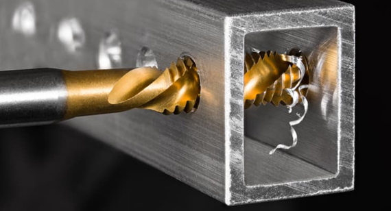
CNC tapping involves cutting internal threads into pre-drilled holes using a tap tool. This automated process ensures precision and consistency across multiple parts. CNC tapping machines can handle various thread sizes and types, making them essential for producing threaded holes in components like engine parts, machinery, and electronics.
Selecting the appropriate hole type is crucial for achieving the desired functionality and manufacturability of a part. Factors such as the hole's purpose, size, material, depth, and production method must be considered to ensure optimal performance and cost-efficiency.
Consider the End Use or Purpose
Understanding the hole's role in the assembly or product is paramount. For fastening applications, tapped holes, counterbores, or countersinks may be necessary. If the hole serves as a passage for fluids or gases, smoothness and diameter consistency become critical.
Determine Size and Shape
The required dimensions and geometry influence the machining process and tools needed. Complex shapes may necessitate CNC milling, while standard cylindrical holes can be efficiently produced through drilling. Tolerances and surface finish requirements also play a significant role in tool selection.
Material Type
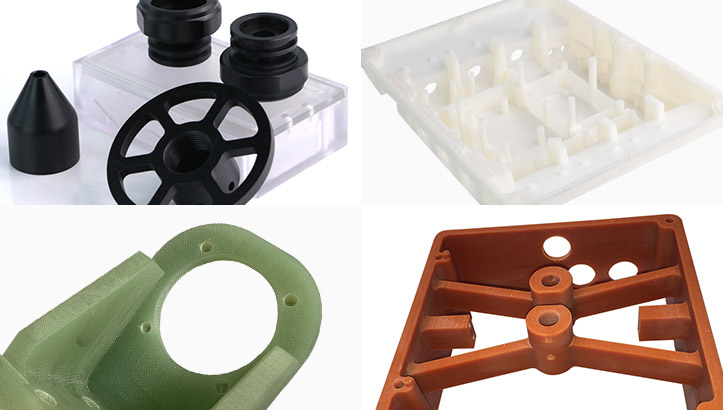
Different materials have varying machinability. Metals may require specific cutting tools and cooling strategies, while plastics might demand lower cutting speeds to prevent melting. Understanding the material's properties helps in choosing the right machining parameters and tools.
Hole Depth
Depth affects the choice of drilling method and tool design. Deep holes may require specialized techniques like gun drilling to ensure straightness and prevent tool deflection. Blind holes necessitate precise depth control to avoid penetrating the material fully.
Power Supply
Certain holemaking processes, like EDM drilling or laser cutting, require specific power sources and equipment. Assessing the availability and suitability of these resources is essential when planning the manufacturing process.
Material selection significantly impacts the drilling process. Each material type presents unique challenges that must be addressed through appropriate tooling, cutting speeds, feeds, and techniques to achieve high-quality holes.
Metals and Alloys
Special Considerations
Tools
Speed
Feed
Plastics
Special Considerations
Tools
Speed
Feed
Composites
Special Considerations
Tools
Speed
Feed
Woods
Special Considerations
Tools
Speed
Feed
| Material |
Special Considerations |
Tooling |
Speed |
Feed |
| Metals & Alloys |
Cooling to prevent overheating, Choose a drill bit according to hardness- Work hardening in ferrous alloys. |
High-speed steel (HSS) or cobalt drill bits, Carbide-tipped bits for hard alloys. |
Low to moderate |
Moderate |
| Plastics |
Avoid melting due to heat, Use sharp, low-friction tools, Avoid tightening of the workpiece to prevent cracking. |
Acrylic or plastic-specific drill bits, Brad-point bits for precision. |
High and it reduces contact time |
Low to moderate |
| Composites |
Minimize delamination by using a backing plate, Avoid excessive force. |
Diamond-coated or carbide drill bits, Use layered comptiable drill bits. |
Low to moderate |
Moderate |
| Woods |
Prevent splintering by supporting the exit side, Consider grain direction, Use sharp tools to avoid burning. |
Prevent splintering by supporting the exit side, Consider grain direction, and Use sharp tools to avoid burning. |
Moderate to high |
Moderate |
Precision in holemaking is achieved through proper fits, dimensioning, and tolerancing. These elements ensure that parts assemble correctly, function as intended, and meet quality standards.
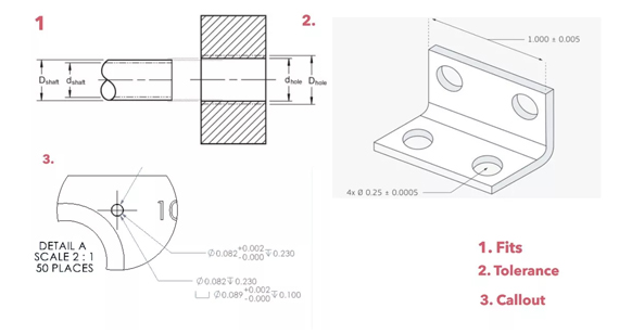
What Are Engineering Hole Fits?
Engineering hole fits describe the relationship between the hole and the mating part (e.g., a shaft or fastener). Fits are classified into:
Standards like ISO and ANSI provide guidelines for these fits, ensuring consistency in manufacturing.
What Are Engineering Hole Dimensionings?
Dimensioning involves specifying the exact measurements of a hole, including diameter, depth, and location. Accurate dimensioning is essential for:
What Are Engineering Hole Tolerances?
Tolerances define the acceptable range of variation in a hole's dimensions due to manufacturing processes. They are crucial for:
Selecting the right tools for drilling is vital for achieving desired hole quality and efficiency. Tools vary based on material, hole type, and production volume.
Drilling Machine
A basic machine for creating holes, ranging from simple drill presses to advanced CNC drilling machines. Suitable for standard drilling operations with straightforward requirements.
CNC Milling Machine
Offers versatility to perform drilling, tapping, reaming, and milling. Ideal for complex parts requiring multiple operations and high precision.
Tapping Tool
Used to cut internal threads within a hole. Tapping can be performed manually or with CNC machines equipped with tapping capabilities.
Reamer
A precision tool used to finish holes to an exact size with a smooth surface. Reaming improves hole accuracy and surface finish after drilling.
Laser Cutting Machine
Uses a focused laser beam to drill holes, especially effective for small or intricate holes in thin materials. Provides high precision and clean edges.
The choice of drilling tool impacts hole quality, tool life, and production efficiency. Factors to consider include material hardness, hole specifications, manufacturing volume, and accuracy requirements.
1. Evaluate Material Hardness
Harder materials require more robust tools like carbide or diamond-coated drills. Softer materials can be drilled with standard HSS tools. Tool material and coating should match the workpiece material to optimize performance.
2. Understand Hole Specifications
Consider diameter, depth, and required surface finish. Specialized drills like gun drills may be necessary for deep holes, while micro drills are used for small diameters.
3. Consider Manufacturing Volume
High-volume production may justify investment in advanced tooling with longer life and higher performance. For low-volume or prototype work, cost-effective standard tools may suffice.
4. Accuracy Requirements
Tight tolerances demand high-quality tools with precise geometry. Reamers or precision boring tools may be needed to achieve the required accuracy and surface finish.
Hole quality is influenced by multiple factors, including tool condition, material properties, machine stability, cutting parameters, and operator skills. Understanding these factors helps in optimizing the drilling process.
Tool Condition
Sharp, well-maintained tools produce cleaner holes with accurate dimensions. Dull or damaged tools can cause oversized holes, poor surface finish, and increased heat generation.
Material Properties
Materials react differently to drilling. Ductile materials may cause chip wrapping, while brittle materials risk cracking. Adjusting cutting speeds and feeds according to material properties is essential.
Machine Stability
Vibration or lack of rigidity in the machine can lead to hole misalignment and poor surface finish. Ensuring the machine is properly set up and maintained enhances drilling accuracy.
Cutting Speeds and Feeds
Optimizing speeds and feeds based on tool and material extends tool life and improves hole quality. Too high speeds can cause overheating, while too low speeds may result in poor chip formation.
Coolant and Lubrication
Using appropriate coolants reduces heat and friction, prevents tool wear, and improves surface finish. Coolant selection depends on the material and drilling operation.
Tool Geometry
Drill point angle, flute design, and overall geometry affect cutting efficiency and chip evacuation. Selecting the right tool geometry for the application enhances performance.
Peck Sequence
Implementing peck drilling cycles helps in deep hole drilling by periodically retracting the drill to remove chips and reduce heat. This prevents tool breakage and improves hole straightness.
Operator Skills
Experienced operators can adjust parameters on-the-fly, detect issues early, and ensure adherence to best practices, significantly impacting the overall quality of the drilled holes.
By understanding these aspects of holemaking in CNC machining, manufacturers can optimize their processes to produce high-quality parts efficiently. Selecting the right hole type, tools, and machining parameters is essential for successful parts manufacturing in custom CNC machining services.
In the realm of mechanical design and manufacturing, holes play a pivotal role in the functionality and assembly of parts. They serve various purposes, from accommodating fasteners and facilitating fluid flow to reducing weight and providing alignment features. However, designing and selecting the appropriate hole types is not a trivial task. It requires a thorough understanding of engineering principles, material properties, machining processes, and the intended application of the part. Making informed decisions in this area can significantly impact the performance, manufacturability, and cost-effectiveness of the final product.
Engineers and designers often face challenges in selecting the right hole types due to the myriad of factors that need to be considered, such as material selection, tolerance requirements, machining limitations, and functional demands. A misstep in this process can lead to increased manufacturing costs, compromised part integrity, or even product failure.
Agitation: Without a comprehensive understanding of these considerations, the risk of encountering issues like improper fits, weakened structures, excessive wear, or manufacturing inefficiencies increases dramatically. This not only affects the quality of the product but can also lead to costly redesigns and production delays.
By delving into the engineering considerations needed when designing and selecting hole types, professionals can make informed choices that enhance product performance, ensure manufacturability, and optimize costs. This article explores critical factors such as material selection, tolerance and precision, hole depth, surface finish, and more, providing a detailed guide to help engineers navigate this complex aspect of design.
Material Selection
Material selection is a fundamental consideration in engineering design, particularly when it comes to hole-making processes in CNC machining parts. The choice of material influences not only the mechanical properties and functionality of the part but also the machining methods, tool selection, and overall manufacturability. Understanding the material's characteristics is essential for designing holes that meet performance requirements while ensuring efficient and cost-effective production.
Hardness and Ductility
Hardness refers to a material's resistance to deformation or indentation. Materials with high hardness, such as hardened steels or certain alloys, present challenges during machining due to increased tool wear and the need for specialized cutting tools. When designing holes in hard materials, engineers must consider:
Ductility is the ability of a material to deform under tensile stress, often characterized by its capacity to stretch into a wire. Ductile materials, such as aluminum or mild steel, are generally easier to machine but may present issues like chip formation and work hardening. Considerations include:
Thermal Properties
Materials respond differently to heat generated during machining, affecting dimensional stability and surface integrity. Thermal considerations include:
Chemical Reactivity
Chemical reactivity impacts material selection, especially when the part will be exposed to corrosive environments or when certain machining fluids may react with the material. Considerations include:
By thoroughly understanding the material properties, engineers can anticipate potential challenges in hole design and machining. This foresight allows for the selection of appropriate machining processes, tools, and design adjustments to ensure that the holes function as intended and that the manufacturing process is efficient and cost-effective.
Tolerance and Precision
Tolerance and precision are critical factors in the design and manufacture of holes in CNC machining parts. Tolerances define the permissible variation in a part's dimensions, ensuring that components fit together correctly and function as intended. Precision relates to the consistency and accuracy of the machining process in achieving those dimensions. Mismanagement of these factors can lead to assembly issues, performance problems, and increased manufacturing costs.
Tool Precision
The precision of the cutting tools used in hole-making directly affects the achievable tolerances. Considerations include:
Machining Setup
The setup of the machining process significantly influences the precision and repeatability of hole-making. Key aspects include:
Measurement and Inspection
Accurate measurement and inspection practices verify that holes meet specified tolerances and identify deviations early in the process. Strategies include:
Understanding and controlling tolerance and precision in hole design and manufacturing is essential for achieving functional and reliable parts. It requires a holistic approach that encompasses tool selection, machining practices, and rigorous inspection protocols. By prioritizing these aspects, engineers and manufacturers can ensure that holes are produced within the required specifications, leading to successful assemblies and satisfied customers.
Determining the appropriate tolerance for a hole is a critical aspect of engineering design. Tolerance defines the acceptable limits of variation in a hole's dimensions, ensuring proper fit, function, and manufacturability. Setting the tolerance too tight may increase manufacturing costs and lead times, while too loose a tolerance can result in poor performance or assembly failures. A balanced approach considers material properties, machining processes, tool condition, machine precision, and the specific requirements of the application.
Material Properties
The material's characteristics influence the achievable tolerances in hole-making. Considerations include:
Machining Process
The chosen machining process affects the precision and repeatability of hole-making. Factors to consider are:
Tool Condition
Tool performance directly impacts hole dimensions. Considerations include:
Machine Precision
The capability of the machining equipment sets the limits for achievable tolerances. Factors include:
Hole Diameter
The size of the hole influences the tolerance decisions. Larger holes may require different considerations compared to smaller ones due to tool deflection, material removal rates, and machining dynamics.
Standardization and Interchangeability
Fit Types and Tolerances
Material Deformation
By systematically evaluating these factors, engineers can determine appropriate hole tolerances that balance functionality, manufacturability, and cost. Collaborating with manufacturing teams and considering real-world process capabilities ensures that the specified tolerances are achievable and practical.
Hole Depth
Hole depth is a crucial consideration in hole design and manufacturing, influencing tool selection, machining strategies, and overall part functionality. Deep holes present unique challenges, such as tool deflection, chip evacuation, and heat management. Understanding these factors allows engineers to design holes that meet functional requirements while ensuring efficient and reliable manufacturing processes.
Tool Accessibility and Clearance
The depth of a hole affects the ability of tools to reach and machine the desired dimensions accurately. Considerations include:
Material Thickness
The thickness of the material relative to the hole depth impacts machining strategies:
Thermal Management and Chip Evacuation
Deep hole drilling generates heat and accumulates chips within the hole, which can affect tool life and hole quality. Strategies to address these challenges include:
By carefully considering hole depth in the design phase, engineers can select appropriate tools and machining methods to produce high-quality holes efficiently. Collaboration with manufacturing specialists ensures that the chosen strategies align with the capabilities of available equipment and processes.
Surface finish refers to the texture and smoothness of a machined surface, including holes. It affects not only the aesthetic appearance but also the functional performance of the part, influencing factors like friction, wear, sealing capabilities, and fatigue life. Achieving the desired surface finish requires careful consideration of material properties, machining techniques, and tool selection.
Functionality
The surface finish of a hole can significantly impact its functional characteristics:
Material Compatibility
Different materials respond uniquely to machining processes, affecting achievable surface finishes:
Manufacturing Techniques
Selecting the appropriate machining techniques is essential for achieving the desired surface finish:
Tool Selection and Geometry: Using tools with the correct geometry, sharpness, and coatings enhances surface quality. For example, polished flutes and cutting edges reduce surface roughness.
Cutting Parameters: Optimizing speeds, feeds, and depth of cut minimizes tool marks and surface irregularities. Slower speeds and finer feeds often improve surface finish.
Finishing Operations: Secondary processes like reaming, honing, or lapping can refine the surface finish of holes beyond what is achievable with drilling alone.
Vibration Control: Reducing machine vibrations through proper fixturing and maintenance prevents surface imperfections caused by chatter.
By integrating surface finish considerations into the design and manufacturing planning, engineers ensure that holes meet both functional and aesthetic requirements. Collaboration between design and manufacturing teams facilitates the selection of appropriate materials, tools, and processes to achieve the desired outcomes.
Tool Accessibility
Tool accessibility is a critical factor in the design and manufacturing of holes in CNC machining parts. It refers to the ability of cutting tools to reach and machine the desired features without obstruction or interference. Poor accessibility can lead to machining difficulties, increased costs, and design compromises. Addressing tool accessibility requires thoughtful consideration of tool dimensions, machine capabilities, and part geometry.
Tool Length and Diameter
Selecting tools with appropriate dimensions is essential for effective machining:
Strategies to optimize tool dimensions include:
Machine Setup
The configuration and capabilities of the CNC machine impact tool accessibility:
Complex Geometry
Parts with complex shapes or internal features present unique challenges:
Addressing tool accessibility in the design phase allows for efficient manufacturing and reduces the risk of costly rework or design changes. Collaboration with manufacturing engineers and considering the capabilities of available equipment ensures that the designed holes can be produced effectively.
Edge Distance
Edge distance refers to the spacing between a hole and the edge of the material or other features. Proper edge distance is crucial for maintaining the structural integrity of the part, ensuring load distribution, and adhering to standard engineering practices. Insufficient edge distance can lead to material failure, while excessive spacing may result in unnecessary material usage or design constraints.
Material Integrity
The proximity of holes to the edge of a part affects its strength and susceptibility to failure:
Load Distribution
Proper edge distance contributes to effective load distribution in assemblies:
Standard Practices
Adhering to established engineering standards and practices ensures consistency and reliability:
By carefully evaluating edge distance in hole design, engineers enhance the structural integrity and performance of the part. Collaboration with structural analysts and adherence to standards ensure that designs meet both functional requirements and industry expectations.
Chip Evacuation
Chip evacuation is the process of removing metal chips or debris generated during machining operations like drilling or milling holes. Effective chip evacuation is essential for maintaining tool life, ensuring surface finish quality, and achieving operational efficiency. Poor chip management can lead to tool breakage, damaged workpieces, and increased production costs.
Tool Life
Proper chip evacuation directly impacts the lifespan of cutting tools:
Surface Finish
The quality of the hole's surface finish is influenced by chip evacuation:
Operational Efficiency
Efficient chip evacuation contributes to smoother and faster machining operations:
Strategies to enhance chip evacuation include:
By prioritizing chip evacuation in the machining process, manufacturers can achieve better tool performance, higher-quality holes, and more efficient production cycles.
Stacked Tolerances
Stacked tolerances refer to the accumulation of dimensional variations that occur when multiple components or features are assembled together. In hole-making, stacked tolerances can significantly impact the overall fit and function of an assembly. Understanding and managing these tolerances is essential to prevent issues like misalignment, interference, or excessive clearance in the final product.
Defining Stacked Tolerances
Stacked tolerances arise when individual tolerances from separate features or parts add up, potentially exceeding acceptable limits:
Impact on Design
Stacked tolerances affect various aspects of design and assembly:
Measurement Techniques
Accurate measurement and control of tolerances help manage stacking effects:
By proactively addressing stacked tolerances in the design and manufacturing process, engineers can prevent assembly issues and ensure that the final product meets performance requirements. Collaboration across design, manufacturing, and quality assurance teams facilitates effective tolerance management.
Corrosion and Wear Resistance
Corrosion and wear resistance are vital considerations in the design and material selection for holes in CNC machining parts. These factors affect the longevity, reliability, and safety of the component, especially in demanding environments or applications involving mechanical stress and exposure to corrosive agents.
Material Selection
Choosing the right material is the first line of defense against corrosion and wear:
Surface Finish
The surface condition of a hole influences its susceptibility to corrosion and wear:
Design Optimization
Thoughtful design can mitigate corrosion and wear risks:
By integrating corrosion and wear resistance considerations into material selection, surface treatment, and design, engineers enhance the durability and reliability of machined parts. This proactive approach contributes to reduced maintenance costs, extended product life, and improved performance in the intended application.
Accurate measurement of hole diameter is essential for ensuring that machined parts meet design specifications and function correctly. Precise measurement techniques enable quality control, facilitate assembly, and support compliance with industry standards. Various tools and technologies are available to measure hole diameter, each suited to specific applications and levels of precision.
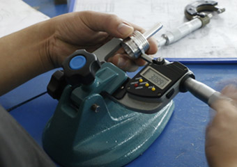
Calipers and Micrometers
Calipers and micrometers are common handheld measuring instruments used for quick and accurate measurements:
Considerations when using calipers and micrometers include:
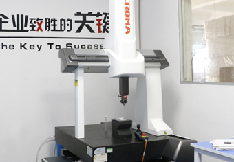
Coordinate Measuring Machines (CMMs)
CMMs are advanced measurement systems that provide highly accurate and automated measurements:
Advantages of using CMMs include:
Laser Scanning and Probes
Advanced technologies like laser scanning and optical probes offer non-contact measurement solutions:
Considerations include:
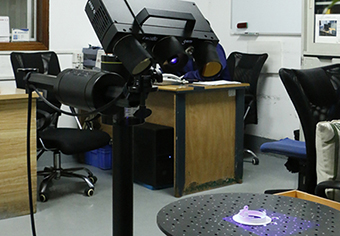
By selecting the appropriate measurement tools and techniques based on the hole's size, precision requirements, and material, engineers and quality control professionals can accurately assess hole dimensions. This ensures that parts meet design specifications, function as intended, and contribute to overall product quality.
Hole specifications, including dimensions, tolerances, surface finish, and material requirements, have a profound impact on the manufacturing process. They influence tool selection, machining strategies, production time, cost, and quality. Understanding these effects enables engineers and manufacturers to optimize processes, balance performance with efficiency, and meet project goals.
Impact on Tool Selection and Wear
1. Tool Compatibility
2. Tool Wear
Cost Impact
1. Material Utilization
2. Cycle Time
1. Tight Tolerances
2. Surface Integrity

By carefully considering how hole specifications influence the manufacturing process, engineers and manufacturers can make informed decisions that optimize efficiency, control costs, and ensure quality. Collaboration between design and production teams facilitates alignment between specifications and practical manufacturing capabilities.
Hole making is a fundamental aspect of CNC machining and parts manufacturing. However, several common mistakes can compromise hole quality, lead to production inefficiencies, or cause part failures. Recognizing and avoiding these pitfalls enhances product quality, reduces costs, and improves overall manufacturing effectiveness.
Inadequate Deburring
Ignoring Hole Roundness
Incorrect Tolerances
Poor Tool Selection
Ignoring Tool Wear
Ignoring Material Properties
By being aware of these common mistakes and implementing preventive measures, manufacturers can improve hole-making processes, resulting in higher-quality parts and more efficient
production cycles.
Advancements in technology continually enhance hole-making processes, offering improved precision, efficiency, and capabilities. Embracing these innovations enables manufacturers to tackle complex challenges, reduce costs, and maintain a competitive edge. Some of the latest developments in hole-making technology include laser drilling, ultrasonic machining, advanced CNC machining, cryogenic drilling, electrochemical machining (ECM), and 3D printing of templates and fixtures.
Laser Drilling
Technology: Utilizes focused laser beams to ablate material and create holes with high precision and minimal mechanical stress.
Advantages:
Applications: Microelectronics, aerospace components, medical devices.
Ultrasonic Machining
Technology: Employs high-frequency vibrations combined with abrasive slurry to erode material and form holes.
Advantages:
Applications: Advanced ceramics machining, precision components.
Advancements:
Impact:
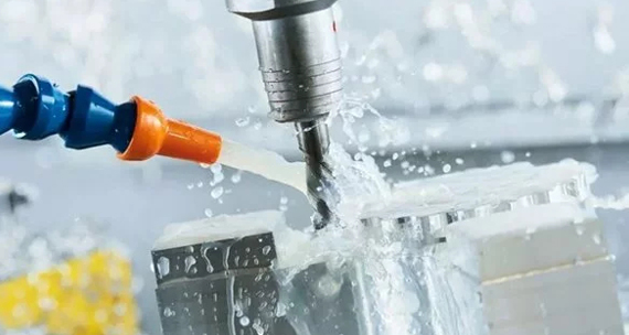
Cryogenic Drilling
Technology: Uses liquid nitrogen or other cryogens to cool the cutting area during drilling.
Advantages:
Applications: Aerospace materials, difficult-to-machine alloys.
Electrochemical Machining (ECM)
Technology: Removes material through anodic dissolution using electrical current and electrolyte solution.
Advantages:
Applications: Turbine blades, medical implants.
3D Printing of Templates and Fixtures
Technology: Additive manufacturing creates custom templates, guides, or fixtures to assist in hole-making processes.
Advantages:
Applications: Complex assemblies, low-volume production.
Embracing these advances allows manufacturers to expand their capabilities, improve quality, and address challenging hole-making requirements in CNC machining parts. Staying informed about emerging technologies supports continuous improvement and innovation in the field.
Understanding the different types of holes in CNC machining is essential for designing functional, cost-effective, and manufacturable parts. By carefully considering hole features, machining processes, and application requirements, engineers and manufacturers can optimize their designs for better performance and efficiency. Whether you're working with custom CNC machining services or producing prototypes, selecting the right hole type is a critical step in successful parts manufacturing.
Designing and selecting hole types in CNC machining involves a complex interplay of engineering considerations, including material selection, tolerance and precision, hole depth, surface finish, tool accessibility, and more. By thoroughly understanding these factors, engineers and manufacturers can create parts that meet functional requirements, are cost-effective to produce, and maintain high-quality standards.
Advancements in hole-making technology offer new opportunities to enhance efficiency, precision, and capabilities. Embracing these innovations, while avoiding common mistakes, ensures that the manufacturing process remains competitive and responsive to evolving industry demands.
Whether dealing with custom CNC machining, CNC prototype machining, or large-scale production, careful attention to hole design and manufacturing considerations is essential for success. By leveraging the insights provided in this article, professionals in the field can make informed decisions that optimize performance and drive excellence in parts manufacturing.
What are the different types of bolt holes?
Bolt holes can be classified into several types, including clearance holes (allowing bolts to pass through without threading), threaded holes (containing internal threads), counterbore holes (with a flat-bottomed enlargement to recess bolt heads), and countersink holes (with a conical enlargement for flush-fitting screw heads).
What is the rule of thumb for hole diameter and edge distance?
A common rule of thumb is that the minimum edge distance should be at least twice the diameter of the hole. This ensures sufficient material strength around the hole to prevent cracking or failure under load.
How to determine clearance hole diameter and tolerance?
Clearance hole diameters are typically slightly larger than the bolt or screw diameter, following standardized charts like those provided by ISO or ANSI. The tolerance depends on the desired fit (loose, normal, or tight) and the specific application requirements.
How to identify holes on engineering drawings?
Holes are identified on engineering drawings using standardized symbols and notations, including diameter (Ø symbol), depth, threading information, and special features like countersinks or counterbores. Detailed dimensioning and annotations provide clear specifications for manufacturing.
What are the different types of hole patterns?
Hole patterns refer to the arrangement of holes on a part and can include linear patterns, circular patterns, grid patterns, or custom arrangements. These patterns are used for functional purposes like fastening, ventilation, or aesthetics.
What are blind holes in manufacturing?
Blind holes are holes that do not pass completely through the material. They have a specific depth and are used when penetration through the entire workpiece is undesirable, such as for threaded holes or when maintaining a sealed surface on one side.
What are tooling holes?
Tooling holes are used during the manufacturing process to aid in alignment, fixturing, or assembly. They serve as reference points or attachment points for tools and are often not part of the final product's functional features.
What is the engineering term for a hole?
In engineering, a hole is often referred to as a "bore" when emphasizing its internal cylindrical shape or as an "aperture" when considering openings in general. Specific terms like "drilled hole," "tapped hole," or "bored hole" provide additional context.
What are the different types of hole cutting tools?
Hole cutting tools include drills (twist drills, spade drills), reamers, taps (for threading), countersinks, counterbores, boring bars, and specialized tools like gun drills or hole saws. The selection depends on the hole type, size, material, and precision requirements.
By addressing these common questions and providing detailed insights into the engineering considerations for hole design and selection, this article aims to support professionals in making informed decisions that enhance the quality and efficiency of CNC machining parts manufacturing.
