16 years one-stop China custom CNC machining parts factory

Hey there I’m VMT Sam!
With 25 years of CNC machining experience we are committed to helping clients overcome 10000 complex part-processing challenges all to contribute to a better life through intelligent manufacturing. Contact us now
 391 |
Published by VMT at Aug 18 2026 | Reading Time:About 7 minutes
391 |
Published by VMT at Aug 18 2026 | Reading Time:About 7 minutes


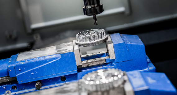
If you are new to CNC milling, it can be easy to focus only on the machine and overlook the details that affect the finished part. Tool access, wall thickness, deep pockets, tolerances, and workholding can change machining difficulty, cost, and quality. Understanding the process helps you design and source parts more confidently.
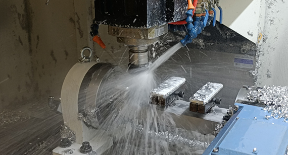
CNC milling, or computer numerically controlled milling, is a machining process that uses computer-controlled rotating multi-point cutting tools to incrementally remove material from a workpiece. It can produce custom-designed parts with flat surfaces, pockets, slots, holes, threads, contours, and complex 3D features in metals and engineering plastics.
This guide explains the milling definition, CNC milling process, machine operation, milling operations, machine types, materials, design considerations, and alternatives, with practical details you can use in real manufacturing projects.
What is milling? Milling is a subtractive machining process that uses a rotating cutter to remove material from a workpiece. Depending on the machine configuration, the cutting tool, workpiece, or both move along controlled axes so that the cutter can create the required surfaces and features.
Milling was originally performed primarily on manually operated machines, and manual milling is still useful for repair work, toolroom adjustments, simple one-off components, and jobs where CNC programming would add unnecessary setup time. However, most precision production milling today is performed on CNC milling machines because computer control makes it easier to repeat toolpaths, coordinate multiple machining operations, and maintain consistent dimensions across multiple parts.
You can use milling to produce flat surfaces, steps, slots, pockets, holes, threads, chamfers, angled features, curved profiles, and complex three-dimensional surfaces. This versatility is why CNC milling is widely used for custom housings, brackets, plates, mounts, fixtures, and other precision machined parts.
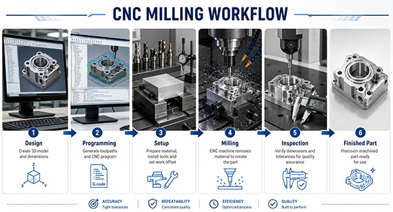
Like other mechanical CNC machining processes, CNC milling uses programmed machine movement to control the relationship between the cutting tool and workpiece. The basic workflow from the original CNC milling process remains straightforward:
1. Design the CAD Model
The CNC milling process usually begins with a 2D drawing, 3D CAD model, or both. Your 3D model defines the part geometry, while the engineering drawing can specify information that may not be obvious from the model, including tolerances, GD&T, datum references, hole specifications, threads, surface roughness, material, and finishing requirements.
This stage is also where manufacturability should be considered. A deep pocket may require a long cutting tool, a very small internal corner radius may force the use of a small end mill, and a thin wall may move under cutting or clamping forces. Identifying these issues before programming can prevent unnecessary machining difficulty later.
2. Convert the CAD Model to a CNC Program
The part model is imported into CAM software, where the programmer selects cutting tools and creates the toolpaths used to machine the part. The program controls factors such as spindle speed, feed rate, depth of cut, machining direction, roughing passes, finishing passes, and tool changes.
The resulting program provides instructions for the CNC machine. Programming is not simply about telling the cutter where to move: toolpath strategy can affect machining time, cutting force, vibration, tool wear, deformation, and surface quality.
3. Set Up the CNC Mill
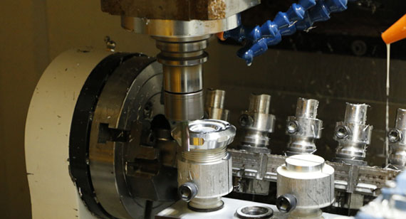
Before the program runs, the workpiece is secured to the machine table or fixture using a vise, soft jaws, clamps, fixture plates, vacuum workholding, or a dedicated fixture. The required cutting tools are loaded into the spindle or tool magazine, and the work coordinate system and tool offsets are established.
Workholding is especially important for thin, long, large, or flexible parts. A fixture must hold your workpiece securely enough to resist cutting forces without applying so much pressure that the part becomes distorted.
4. Perform the Milling Operations
Once the machine is prepared, the operator starts the program and the cutting tool rotates while controlled machine movements bring it into contact with the workpiece. Material is removed as chips until the required geometry is produced.
Most parts are not machined to their final dimensions in one pass. Rough machining first removes the majority of unwanted material while leaving controlled stock on important surfaces. Finishing operations then bring critical features such as datum faces, bores, mating surfaces, threads, and profiles to their final dimensions and surface requirements.
5. Deburr and Inspect the Part
Milling can leave burrs around holes, slots, threads, cross-hole intersections, and sharp edges. These must be controlled because even a small burr can affect assembly or interfere with a mating feature.
Inspection may then use calipers, micrometers, height gauges, pin gauges, thread gauges, optical measurement, surface roughness testing, or CMM measurement depending on the drawing requirements.
6. Apply Surface Finishing
If your CNC milled part requires anodizing, passivation, plating, bead blasting, polishing, powder coating, PVD, or another finish, the finishing requirements should ideally be considered before the machining process is finalized. Coating thickness, masking, cosmetic surfaces, threaded holes, press fits, sealing faces, and electrical contact areas can all affect how the part should be machined.
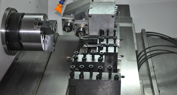
A CNC milling machine uses a rotating cutting tool and programmed machine movements to create the required geometry. Depending on the machine, the cutter can move relative to a fixed workpiece, the workpiece can move relative to the cutter, or both can move.
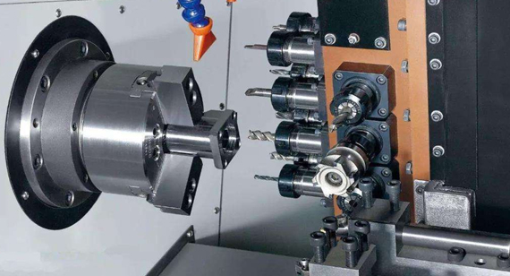
Modern machining centers can also perform several processes during the same setup, including milling, drilling, boring, reaming, tapping, thread milling, and chamfering. Automatic tool changers allow one machine to switch between different cutters as the program progresses.
The major components you will encounter include:
For most customers, you do not need to know every internal component of the machine. What matters more is whether the selected CNC milling machine, cutting tools, fixture, and machining strategy can reach your features and maintain the dimensional relationships required by your drawing.
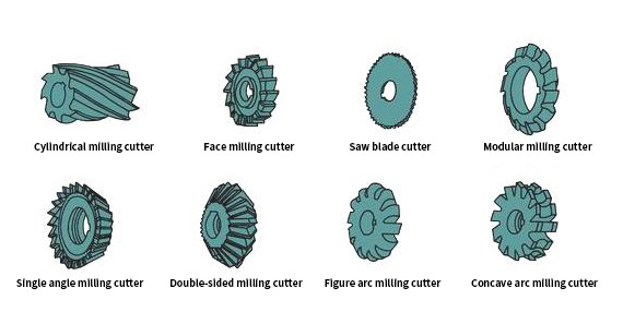
Common CNC Milling Cutters
Different features require different cutters, and tool size can directly influence what geometry is practical to machine.
| Cutting Tool | Typical Use |
| Face Mill | Large flat surfaces and datum faces |
| Flat End Mill | Pockets, slots, side walls, profiles |
| Ball Nose End Mill | Curved and 3D surfaces |
| Bull Nose End Mill | Contours with a controlled corner radius |
| Chamfer Mill | Chamfers, edge breaking, deburring |
| Drill | Producing holes |
| Reamer | Improving hole size and finish |
| Thread Mill | Producing internal or external threads |
A smaller cutter can reach smaller details, but it also has less rigidity than a larger tool. This is why extremely small internal radii, narrow slots, and deep small-diameter features often take longer to machine.
Spindle Speed, Feed Rate, and Depth of Cut
Spindle speed is how fast the cutter rotates, normally measured in revolutions per minute. Feed rate describes how quickly the tool moves through the workpiece, while depth of cut determines how much material is removed in a pass. These parameters must be considered together with the tool diameter, cutter material, workpiece material, machine rigidity, and machining operation.
There is no single “best” speed or feed that applies to every CNC milled part. Cutting too aggressively can increase tool load, vibration, heat, and deflection, while an unsuitable low feed can cause rubbing and unnecessary heat or tool wear.
CNC milling includes several different cutting operations. The appropriate method depends on the surface or feature you need to produce.
Face Milling
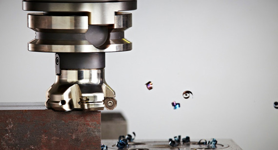
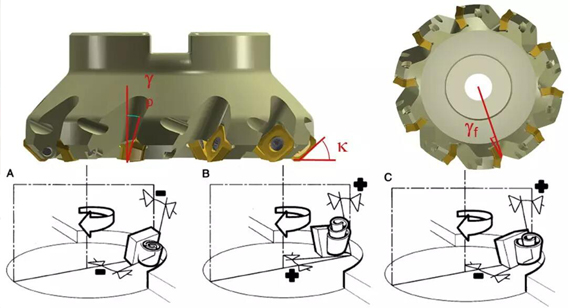
Face milling is performed with the cutting tool axis generally perpendicular to the machined surface. Cutting edges on the face and periphery of the cutter remove material to produce broad flat surfaces.
You commonly use face milling for datum faces, mounting surfaces, sealing surfaces, and stock preparation. A roughing pass may first remove more material, followed by a finishing pass using suitable cutting conditions to improve flatness and surface quality.
Peripheral or Plain Milling
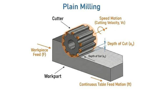
Peripheral milling uses cutting edges around the circumference of the cutter, with the cutter axis generally parallel to the machined surface. It can be used for side surfaces, steps, shoulders, and straight external features.
Angle Milling
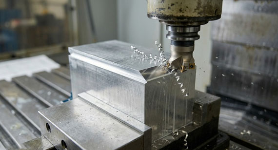
Angle milling produces features at an angle to the main workpiece surfaces. Depending on the geometry, it may use an angled cutter, chamfer mill, dovetail cutter, or multi-axis tool orientation.
Typical features include chamfers, dovetails, V-grooves, and angled surfaces. On modern CNC machines, some angular features that once required dedicated form cutters can also be machined by repositioning the tool or workpiece.
Form Milling
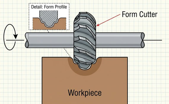
Form milling uses a cutter whose cutting profile helps generate a specific contour or shape. It can be used for concave, convex, radius, and other formed surfaces.
For complex freeform geometry, modern CNC machining often combines ball nose or radius cutters with programmed contour toolpaths rather than relying entirely on a single dedicated form cutter.
Pocket Milling
Pocket milling removes material inside a closed boundary to create cavities commonly found in housings, fixtures, brackets, and lightweight structural parts. As a pocket becomes deeper and narrower, the required cutter reach increases, reducing tool rigidity and increasing the risk of chatter, deflection, poor surface finish, and dimensional variation.
If your design allows it, reducing unnecessary depth or increasing the internal corner radius can make a deep pocket easier and less expensive to machine.
Slot Milling
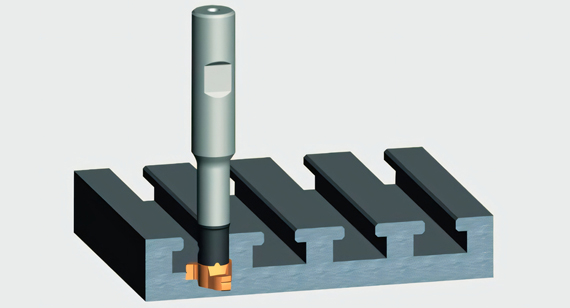
Slot milling creates channels, keyways, adjustment slots, cable channels, and similar narrow features. Narrow and deep slots require careful tool selection because chip evacuation and cutter rigidity become more difficult as the depth-to-width ratio increases.
Contour Milling
Contour milling follows vertical, inclined, curved, or freeform surfaces. It is commonly used for product housings, optical components, robotics parts, molds, and other parts with complex 3D profiles.
Roughing, semi-finishing, and finishing may use different cutters and stepovers to balance material removal with final surface quality.
In addition to the common operations above, milling machines can perform several specialized machining operations.
Climb Milling vs Conventional Milling
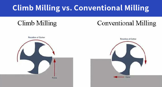
The older page also discussed climb and conventional milling, but the cutting relationship is worth clarifying.
In climb milling, the cutter rotation at the point of contact follows the same general direction as the feed, and chip thickness decreases as the tooth moves through the cut. In conventional milling, the cutting action opposes the feed direction and chip thickness increases through the cut.
Modern CNC machines frequently use climb milling when machine rigidity, workholding, material, and toolpath allow it, but the correct strategy depends on the actual machining conditions.
Milling machines are commonly differentiated by spindle orientation and the number of controlled axes.
On a vertical milling machine, the spindle is primarily oriented vertically. Vertical machining centers are commonly used for brackets, plates, covers, housings, pockets, and general precision components.
A horizontal milling machine uses a primarily horizontal spindle orientation. Depending on the machine configuration, horizontal machining can be useful for heavier cutting, multi-side access, production work, and chip evacuation.
When selecting a machine, you should consider part size, weight, number of machined sides, required tool access, tolerance relationships, production quantity, and workholding—not simply whether the machine is horizontal or vertical.
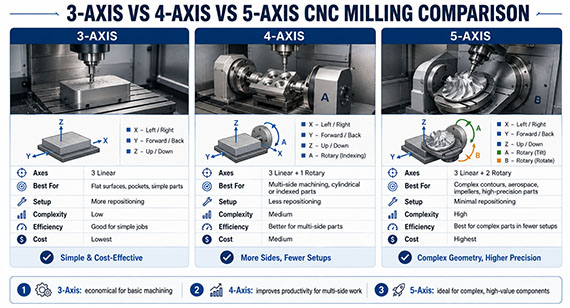
3-Axis CNC Milling
A 3-axis CNC milling machine controls linear movement along the X, Y, and Z axes. It can handle a large percentage of common CNC milled components, including flat plates, brackets, pockets, fixtures, and straightforward housings.
3-axis machining is not inherently low in quality or accuracy. When your geometry can be accessed efficiently from simple orientations, a properly planned 3-axis process can be the most practical and economical solution.
4-Axis CNC Milling
4-axis machining adds a rotary axis to X, Y, and Z movement. It can rotate or index the workpiece so features on multiple sides can be machined with fewer manual repositioning steps.
This is useful for circular hole patterns, repeated side features, cylindrical components requiring milled details, and other parts where controlled rotation improves access.
5-Axis CNC Milling
5-axis CNC machining combines three linear axes with two rotational axes, allowing complex surfaces and multi-angle features to be reached from more directions.
In 3+2 machining, the rotary axes position your part at a fixed angle and three-axis cutting then takes place from that orientation. In simultaneous 5-axis machining, the linear and rotary axes can move together during cutting.
Five-axis machining can reduce setups and improve access to complex geometry, but it is not automatically the best process for every component. A simple part that can be machined efficiently in three axes does not benefit from additional machine complexity simply because five-axis equipment is available.
For reference, the standard CNC axis notation normally uses X, Y, and Z for linear movement, while A, B, and C describe rotation around X, Y, and Z respectively. The axis configuration varies between machine designs, so it is more useful to evaluate available tool orientations than to assume every machine uses the same physical layout.
In addition to vertical, horizontal, and axis-based classifications, milling machines have traditionally been divided into knee-type, ram-type, bed-type, and planer-type designs.
A knee-type milling machine uses a vertically adjustable knee supporting the saddle and table. These machines are common in manual machining, repair, and toolroom environments.
A ram-type milling machine supports the spindle or milling head on a movable ram, providing additional positioning flexibility.
A bed-type milling machine uses a more rigid machine structure with the table supported directly by the bed. Many modern production machining centers follow variations of this rigid construction because it supports stable, higher-load machining.
A planer-type mill is designed for larger workpieces and may use multiple cutting heads to machine large surfaces.
Other specialized designs include rotary-table, drum, and purpose-built production milling machines. For most customers ordering custom CNC milled parts, however, the most important questions are usually machine working envelope, spindle capability, axis configuration, fixture strategy, tolerance capability, and access to your part features, rather than the traditional machine classification alone.
CNC milling can machine a wide range of metals and engineering plastics. Your material choice affects cutting tools, machine settings, cutting speed, feed rate, depth of cut, tool wear, heat generation, surface finish, deformation behavior, and machining cost.
| Material | Why You May Choose It | Main Milling Consideration |
| Aluminum | Lightweight, corrosion resistant, machinable | Thin walls and heavy pocketing can deform |
| Stainless Steel | Strength, corrosion resistance, durability | Heat and tool wear require controlled cutting |
| Carbon / Alloy Steel | Strength and wear resistance | Hardness strongly affects machinability |
| Brass | Good machinability and metallic appearance | Often suitable for fittings and precision hardware |
| Copper | Electrical and thermal conductivity | Tool geometry and surface requirements need attention |
| Titanium | High strength-to-weight ratio, corrosion resistance | Heat and tool wear make machining more demanding |
| POM | Stable, low friction | Thin features can deform during clamping |
| PEEK | High-performance engineering plastic | Material cost increases the importance of process planning |
| Nylon | Tough and lightweight | Moisture and dimensional stability should be considered |
| PMMA | Transparent, cosmetic applications | Scratching, heat, and cracking require control |
Aluminum 6061 and 7075 are widely used for CNC milling because they combine useful mechanical properties with good machinability, although the correct alloy should be chosen from your strength, weight, finishing, corrosion, and cost requirements rather than machining alone.
Stainless steel can provide better corrosion resistance and strength for many applications but generally requires more attention to cutting heat and tool wear. Titanium provides high strength with relatively low density and good corrosion resistance, but it is more demanding to machine because heat and cutting conditions must be carefully controlled.
Engineering plastics such as POM, PEEK, nylon, ABS, and PMMA can also be CNC milled, but they respond differently to heat and clamping force than metals. You can review additional grades through VMT's CNC machining materials resource.
CNC milling can produce precision components, but there is no single tolerance that applies to every milled part. Achievable accuracy depends on material, part size, feature size, geometry, wall thickness, tool length, machine rigidity, workholding, temperature, machining sequence, and inspection method.
You should concentrate tight tolerances on features that affect function, such as locating holes, bearing bores, sealing surfaces, mating interfaces, precision datums, and assembly-critical relationships. Applying the same tight tolerance to every surface can increase machining time and inspection cost without improving how your product works.
For suitable precision applications, VMT can support machining tolerances down to approximately ±0.005 mm and machined surface roughness as fine as Ra 0.2 μm, but these values should not be treated as universal specifications for every geometry or material. Your actual drawing needs to be reviewed feature by feature.
Tip: Ask whether a dimension affects fit, alignment, sealing, motion, or assembly. If it does not, a more practical tolerance may reduce cost and manufacturing risk.
CNC milling is widely used because you can manufacture complex custom geometry without first investing in dedicated production tooling such as a mold or die. A single process can create flat surfaces, holes, pockets, threads, angled features, and 3D contours, while CNC programming makes the process repeatable for additional parts.
It is particularly useful when you need:
Once the design, toolpaths, fixtures, and inspection requirements are validated, the same fundamental manufacturing process can also support repeat production.
Understanding the limitations of CNC milling can help you improve your design before machining begins.
Internal Corners
A round end mill naturally leaves a radius in an internal corner. If you specify an extremely small radius, a smaller cutting tool may be required, reducing rigidity and increasing machining time.
Where your design allows it, use a larger internal radius rather than making every pocket corner as sharp as possible.
Deep Pockets
A deep pocket often requires a long-reach cutter. As tool overhang increases, rigidity decreases and the risk of chatter, deflection, poor surface finish, and dimensional variation increases.
If the function allows, increasing pocket width, increasing internal radii, or reducing unnecessary depth can improve manufacturability.
Thin Walls
Thin walls can move because of cutting force, clamping pressure, heat, or released material stress. Their manufacturability depends not only on wall thickness but also on wall height, material, geometry, machining sequence, and required tolerance.
Tool Access
The cutting tool must physically reach the feature. Deep side features, undercuts, hidden cavities, and angled holes may require additional setups, specialized tooling, 4-axis or 5-axis machining, or another manufacturing process.
Holes and Threads
Use standard drill and thread sizes where your design allows it. A threaded feature should also be evaluated for depth, entry, position, surrounding wall thickness, and any later coating that may affect thread fit.
Surface Finishing
If your part will be anodized, plated, coated, polished, or bead blasted, identify masking areas, cosmetic surfaces, sealing faces, threads, and precision fits before machining is finalized.
A part can look straightforward in CAD and still become difficult to control during machining. The following issues are especially common in precision CNC milling.
Part Deformation
Thin-wall housings, heavily pocketed components, and large plates can change shape during or after machining because material removal changes the stress balance of the part. Balanced roughing, controlled fixture pressure, suitable toolpaths, leaving finishing allowance, and machining critical dimensions later can help reduce this risk.
Chatter and Vibration
Chatter can occur when the cutter, workpiece, or fixture lacks sufficient rigidity. Long tool overhang, deep cavities, thin walls, unsuitable cutting parameters, and poor workholding can all contribute. The solution normally requires evaluating tool length, tool diameter, cutting engagement, spindle speed, feed, and fixture support together.
Burrs
Burrs frequently occur around drilled holes, slots, threads, cross-hole intersections, and thin edges. They should not be treated only as cosmetic defects because a burr can prevent a screw from starting correctly, interfere with a mating component, or create handling problems.
Flatness Variation
Removing large amounts of material from one side of a plate or housing can release residual stress. Rough machining, repositioning, controlled finishing, and suitable material condition may be needed when flatness is critical.
Hole Accuracy
A precision hole may require more than the correct diameter. Position, perpendicularity, roundness, depth, and relationship to other datums may also determine whether the part assembles correctly.
Thread Quality
Thread problems can come from incorrect depth, burrs, poor thread entry, tool wear, positional error, or coating buildup. For assembly-critical threads, functional thread gauges can verify whether the finished feature actually mates as intended.
CNC milling is highly flexible, but it is not automatically the best process for every part. Your geometry, material, tolerance, production quantity, lead time, and tooling budget determine which manufacturing method makes the most sense.
| Manufacturing Process | Best Suited For | Main Advantage | Main Limitation Compared With CNC Milling |
| CNC Milling | Precision custom parts, prototypes, pockets, holes, complex multi-sided geometry | No production mold required and easy to modify | Material is removed as chips and complex parts can require longer machining time |
| CNC Turning | Shafts, pins, bushings, and other rotational parts | Efficient for cylindrical geometry | Less suitable for complex multi-sided features without secondary milling |
| 3D Printing | Rapid prototypes and complex internal geometry | Minimal tooling and strong geometric freedom | Surface finish, material properties, and dimensional accuracy may not match machined parts |
| Die Casting | High-volume aluminum or zinc parts | Low unit cost after production tooling is established | Requires mold investment and design changes are more expensive |
| Sheet Metal Fabrication | Thin covers, panels, brackets, and bent enclosures | Efficient for thin-walled structures | Not suitable for thick solid geometry, deep precision pockets, or complex 3D machined features |
| Injection Molding | High-volume plastic parts | Very low unit cost at large quantities | Mold cost and lead time make it less flexible for prototypes and frequent design changes |
| EDM | Sharp internal features and hard-to-reach conductive-material geometry | Can produce features that rotating cutters cannot reach | Usually slower and limited to electrically conductive materials |
If your part is primarily cylindrical, CNC turning may be more efficient. If you need a thin bent enclosure, sheet metal fabrication may be a better choice. If you expect very high production volumes, die casting or injection molding may eventually reduce unit cost after tooling investment.
CNC milling is particularly useful when you need production-grade material, dimensional accuracy, design flexibility, complex machined features, and low- to medium-volume production without investing in dedicated tooling.
For some parts, the best solution is not one process alone. A cylindrical component may be turned first and then milled to create flats, cross holes, slots, or mounting features, while difficult internal geometry may require EDM as a secondary operation.
Tip: Choose the manufacturing process from what your part needs to do, not from the process you originally expected to use.
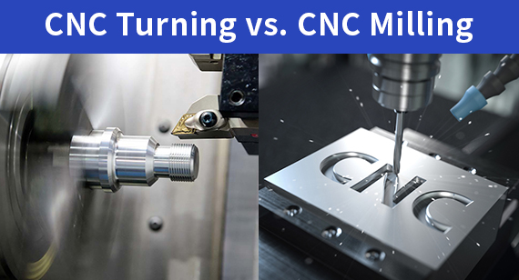
The simplest difference between CNC milling and CNC turning is the primary rotating element:
In CNC milling, the cutting tool rotates. In CNC turning, the workpiece rotates.
| Feature | CNC Milling | CNC Turning |
| Main rotating element | Cutting tool | Workpiece |
| Typical geometry | Prismatic, multi-sided, irregular | Cylindrical, rotational |
| Common features | Pockets, slots, flats, holes, contours | Diameters, bores, grooves, tapers |
| Typical parts | Housings, brackets, plates | Shafts, pins, bushings |
| Multi-sided features | Well suited | Often requires secondary milling |
If your component combines both rotational and non-rotational geometry, it may be produced through separate milling and turning operations or on turn-mill equipment.
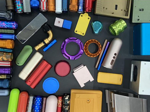
CNC milling can leave your part in an as-machined condition, or you can apply a secondary surface finish to improve appearance, corrosion resistance, wear resistance, surface texture, or other functional requirements. The right finish depends on your material and how the finished part will be used.
| Surface Finish | Common Materials | Why You May Use It |
| Anodizing | Aluminum | Corrosion resistance, wear improvement, decorative color |
| Hard Anodizing | Aluminum | Higher surface hardness and wear resistance |
| Bead Blasting | Aluminum, stainless steel, titanium | Uniform matte texture and reduced visible machining marks |
| Brushing | Aluminum, stainless steel | Controlled directional appearance |
| Polishing | Aluminum, stainless steel, brass | Smoother or more reflective surface |
| Passivation | Stainless steel | Supports corrosion resistance without adding a thick coating |
| Electroless Nickel Plating | Aluminum, steel, brass and selected metals | Uniform metallic coating for corrosion, wear, or functional requirements |
| Powder Coating | Aluminum, steel | Protective colored coating |
| PVD | Stainless steel, titanium and selected metals | Decorative color, wear-related properties, premium appearance |
| Laser Marking | Metals and selected plastics | Part numbers, logos, identification, traceability |
Surface finishing should be considered before CNC milling is finalized, not after the part is already complete. Anodizing, plating, and coating can affect thread fit, mating dimensions, press fits, sealing surfaces, electrical contact areas, and cosmetic requirements.
For example, if an anodized aluminum housing contains a precision mating pocket and several threaded holes, you may need to specify which surfaces are coated, masked, or dimensioned after considering the coating thickness. Otherwise, a part that passed dimensional inspection before finishing may not assemble correctly afterward.
You can review additional options through VMT's surface finishing services when selecting a finish for your material and application.
Note: Do not select a surface finish only because of its appearance. First consider whether it will affect the dimensions, friction, conductivity, corrosion resistance, sealing, or assembly of your finished part.
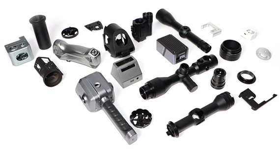
CNC milling is used across many industries because you can machine production-grade metals and plastics while controlling pockets, holes, threads, mating surfaces, multi-sided features, and complex geometry without requiring dedicated production tooling.
| Industry | Common CNC Milled Parts | Why CNC Milling Is Used |
| Automotive | Brackets, housings, test components, fixtures, development parts | Supports prototypes, low-volume development, precision interfaces, and frequent design changes |
| Electronics | Enclosures, frames, heat sinks, connector housings, mounting components | Suitable for thin-wall housings, internal pockets, threaded features, and cosmetic metal finishes |
| Robotics & Automation | Motor mounts, sensor brackets, joints, structural plates, fixtures | Supports multi-sided geometry, accurate mounting relationships, and custom mechanical interfaces |
| Medical & Laboratory Equipment | Instrument components, housings, fixtures, mounts | Useful for precision features, engineering materials, controlled surface finishes, and detailed inspection requirements |
| Camera & Optical Equipment | Camera housings, lens mounts, tripod adapters, optical brackets | Helps control alignment, mounting interfaces, concentricity, surface quality, and compact complex geometry |
| Aerospace & UAV | Lightweight brackets, housings, mounts, structural components | Suitable for high-strength lightweight materials and complex multi-angle geometry |
| Industrial Equipment | Machine components, guides, fixtures, covers, mounting plates | Allows custom geometry, durable engineering materials, replacement parts, and repeatable machining |
The same CNC milling process can solve very different manufacturing requirements. An electronics housing may depend on thin-wall stability and cosmetic anodizing, while an optical mount may depend more on datum relationships, alignment, and bore position.
This is why you should not evaluate CNC milling only by asking whether the machine can produce the shape. You should also consider whether the process can maintain the functional relationships that matter in your final assembly.
Two CNC milled parts made from the same material can have very different costs because raw material is only one part of the calculation.
Machining cost is affected by part size, material machinability, volume of material removed, number of setups, cutting-tool access, tolerance requirements, surface roughness, inspection, secondary finishing, and production quantity.
For example, a simple aluminum plate with several drilled holes may require little programming and machining time, while a thin-wall housing made from the same alloy may require extensive pocket roughing, multiple tools, controlled workholding, tight flatness, cosmetic finishing, and additional inspection.
You can often reduce CNC milling cost by:
The goal is not to make your design less precise. It is to apply precision where it adds real value to the part.
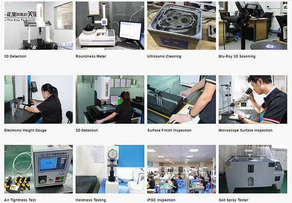
Quality control begins before the finished part reaches the inspection room. A stable CNC milling process should connect the drawing requirements with the datum strategy, fixture, machining sequence, cutting tools, in-process checks, and final inspection.
For simple dimensions, conventional inspection tools may be sufficient. Complex positional relationships, profiles, and tight geometric requirements may require CMM or optical measurement. Critical threads may be checked using functional gauges, while surface requirements can require roughness measurement and visual inspection.
At VMT, quality control can include DFM review, dimensional inspection, in-process quality checks, CMM inspection, thread gauges, surface roughness testing, and final inspection according to your drawing requirements.
If your part has a tight tolerance, do not focus only on whether the final dimension can be measured. You should also consider whether the machining process can maintain that feature consistently across the required production quantity.
CNC milling can support the same project through several development stages.
During the prototype stage, you can evaluate geometry, fit, material, assembly, and function. After testing, you may revise wall thickness, hole positions, tolerances, internal radii, or surface finishing requirements.
A pilot batch then helps confirm fixture repeatability, tool life, inspection methods, surface finishing consistency, and whether the process remains stable when several parts are produced rather than only one.
Once these requirements are validated, the CNC program, fixtures, tooling, inspection criteria, finishing specifications, and packaging can be standardized for repeat production.
CNC milling starts with a simple principle—a rotating cutter removes material from a workpiece—but the quality and cost of a finished part depend on much more than the machine itself. Tool access, internal radii, pocket depth, wall thickness, material, tolerances, workholding, machining sequence, finishing, and inspection all influence how your design should be manufactured.
If you are learning about CNC milling because you have a real part to produce, you do not need to become a machining expert before contacting a supplier. What matters is understanding enough to recognize which requirements affect function and which design choices may create unnecessary machining difficulty.
If you are unsure whether your part should use 3-axis, 4-axis, or 5-axis CNC milling, or you have questions about a deep pocket, thin wall, tolerance, thread, material, or surface finish, you can send your 2D drawing and 3D CAD model to VMT. We can review the manufacturing requirements and provide DFM feedback before you move into prototype or production.
Upload your 2D/3D drawings to request a CNC milling quote and manufacturing review.
Send your drawings, requirements, and target quantity. VMT will review your project and provide a machining solution and quote.
All information and uploaded files are secure and confidential.
1 Tell us what you need
2 Get solution & quote
3 Approve production
Email: inquiry@vimetal.com.cn
What is CNC milling in simple terms?
CNC milling uses a computer-controlled machine and rotating cutting tool to remove material from a workpiece until the required part shape is produced.
What does CNC stand for?
CNC stands for Computer Numerical Control, meaning programmed numerical instructions control the movement and functions of the machine.
What is a CNC milling machine?
A CNC milling machine is a computer-controlled machine tool that uses rotating cutters and controlled axis movement to machine features such as flat surfaces, pockets, slots, holes, threads, and complex contours.
What is the difference between 3-axis and 5-axis CNC milling?
A 3-axis machine primarily controls X, Y, and Z linear movement. A 5-axis machine adds two rotational axes, providing additional tool orientation for complex, angled, or multi-sided geometry.
Is 5-axis CNC milling always better than 3-axis milling?
No. A part that can be machined efficiently on a 3-axis machine may not gain any useful benefit from 5-axis machining. The machine should be selected according to geometry, tool access, tolerance relationships, setup requirements, and cost.
Can CNC milling produce sharp internal corners?
A conventional round end mill naturally leaves an internal corner radius. If your design requires a truly sharp internal corner, you may need a design change or another process such as EDM.
Can CNC milling produce thin-wall parts?
Yes, but thin walls require more attention to cutting force, clamping pressure, material stress, toolpaths, and machining sequence because they are more likely to deform.
What materials can be CNC milled?
Common materials include aluminum, stainless steel, steel, brass, copper, titanium, POM, PEEK, nylon, ABS, PMMA, and many other machinable engineering materials.
How precise is CNC milling?
CNC milling can achieve tight dimensional control, but actual accuracy depends on material, geometry, feature size, workholding, tool length, machining strategy, machine capability, and inspection method.
Can CNC milled parts be anodized or plated?
Yes. Depending on the material, CNC milled parts can be anodized, hard anodized, plated, passivated, bead blasted, brushed, polished, powder coated, PVD coated, or otherwise finished after machining.
Is CNC milling suitable for prototypes?
Yes. CNC milling is well suited to functional prototypes because you can machine parts directly from engineering materials without first investing in a production mold.
Can CNC milling be used for production?
Yes. CNC milling can support prototypes, low-volume manufacturing, and repeat batch production. For very high production quantities, you should also compare the economics of processes such as casting, forging, stamping, extrusion, or molding.


 +86 15099911516




 Read more